Power systems and methods for high or medium initial temperature heat sources in medium and small scale power plants
- Summary
- Abstract
- Description
- Claims
- Application Information
AI Technical Summary
Benefits of technology
Problems solved by technology
Method used
Image

Examples
first embodiment
Third Alternate of First Embodiment
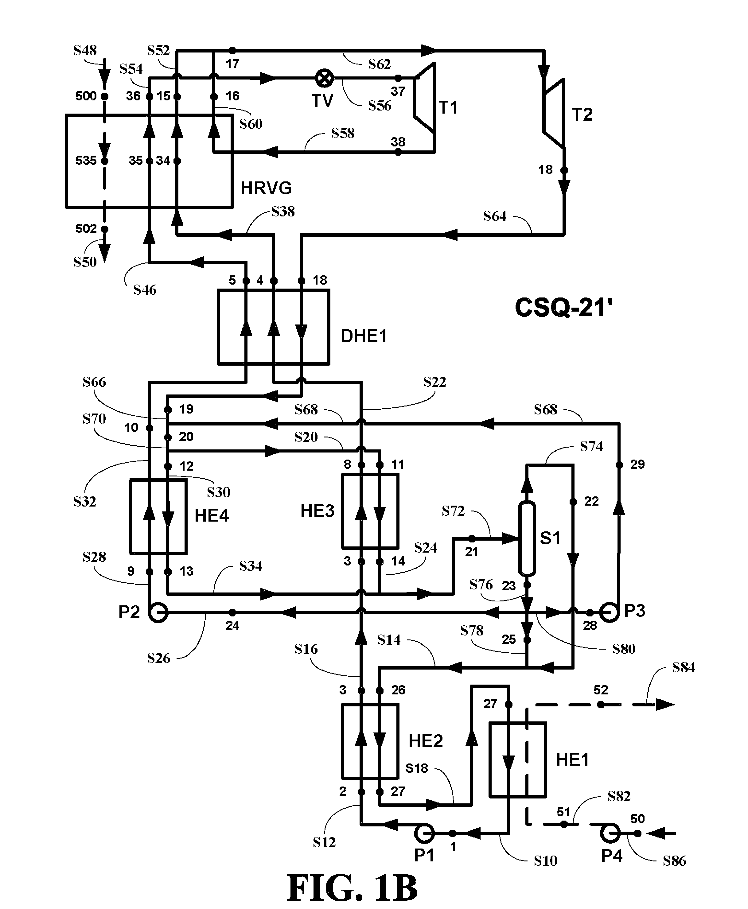
[0038]In yet another alternate embodiment of the system of this invention shown in FIG. 1D, the heat exchanger HE5 and HE6 are combined into a first single, dual flow heat exchanger DHE1 and the heat exchanger HE3 and HE4 are combined into a second single, dual flow heat exchanger DHE2.
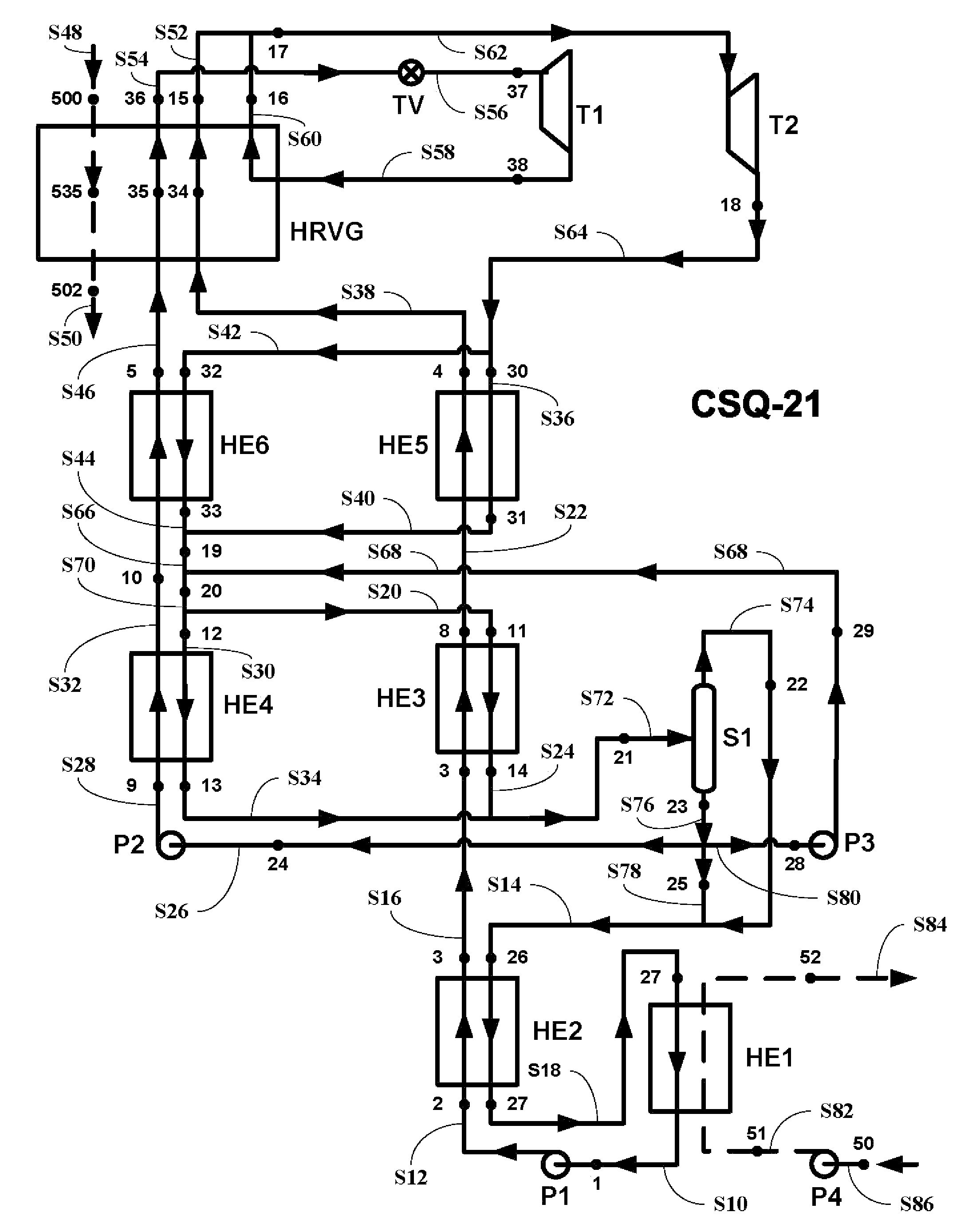
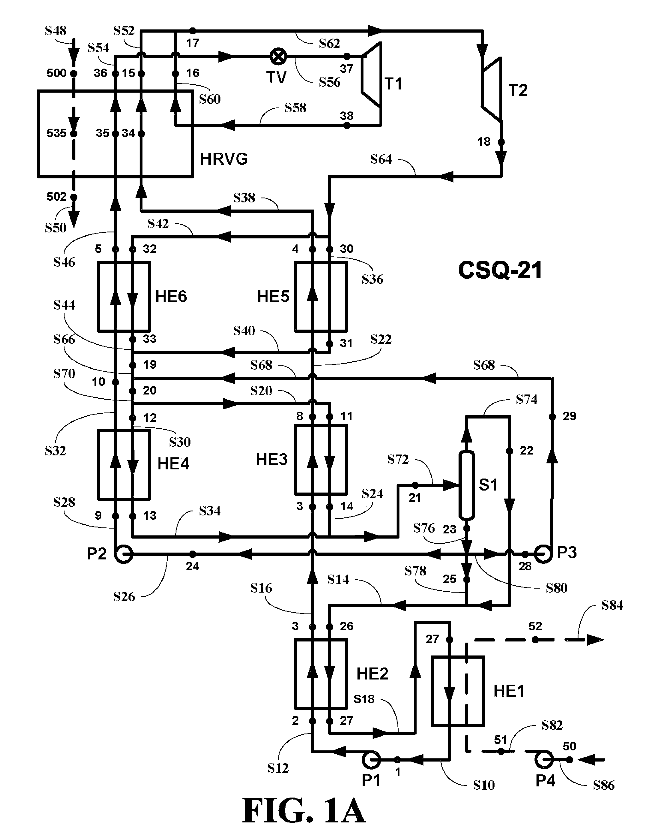
[0039]The combined de-superheated stream S66 having the parameters as at the point 19 is in a state of slightly superheated vapor. At this point, the combined de-superheated stream S66 having the parameters as at the point 19 is mixed with a pressurized liquid stream S68 having parameters as at a point 29 as described below forming a saturated vapor stream S70 having parameters as at a point 20.
[0040]The saturated vapor stream S70 having the parameters as at the point 20 is then divided into the first substream S30 having parameters as at a point 12 and the second substream S20 having parameters as at the point 11. The second substream S20 having parameters as at the...
second embodiment
[0050]The system of this invention can also be embodied in a simplified version (designated CSQ-21s) using only one a single turbine. The simplified version can utilize high or medium temperature heat source and is depicted in FIG. 2.
[0051]This simplified embodiment of the system of this invention operates in a manner identical to the embodiment of FIG. 1 described above, until it deviated at the stream S28 having the parameter as at the point 9.
[0052]In the simplified embodiment of the system of FIG. 2, the pressure at the stream S28 having the parameter as at the point 9 is approximately the same as the pressure of the stream S16 having the parameters at the point 3, in distinction to the embodiment of FIG. 1, where the pressure of the stream S28 having the parameter as at the point 9 is substantially higher than the pressure of the stream S16 having the parameters at the point 3.
[0053]Thereafter, the stream S28 having the parameter as at the point 9 enters into the fourth heat ex...
third embodiment
[0059]In an alternate embodiment, the heat source stream S48 having the parameters as at the point 500 pass through the tubes of the HRVG. In such an arrangement, the stream S38 having the parameters as at the point 4 and the stream S46 having the parameters as at the point 5 can be combined into a single stream S98 having parameters as at a point 42 before entering into the HRVG as shown in FIG. 3. This variant is referred to as variant CS-21a. This combined stream S98 having the parameters as at the point 42, then exits the HRVG as the vaporized and superheated stream S62 having the parameters as at the point 17.
[0060]This simplified version of the system has a lower efficiency than the embodiments of FIG. 1 and FIG. 2 described above, but is substantially simpler (having just one turbine) and is able to work with a wider range of initial heat source temperatures.
[0061]The embodiments of FIG. 2 and FIG. 3 can also be altered as set forth in FIGS. 1B-D.
Efficiencies and Cost Savings...
PUM
 Abstract
Description
Claims
Application Information
 - R&D
- Intellectual Property
- Life Sciences
- Materials
- Tech Scout
- Unparalleled Data Quality
- Higher Quality Content
- 60% Fewer Hallucinations
Browse by: Latest US Patents, China's latest patents, Technical Efficacy Thesaurus, Application Domain, Technology Topic, Popular Technical Reports.
© 2025 PatSnap. All rights reserved.Legal|Privacy policy|Modern Slavery Act Transparency Statement|Sitemap|About US| Contact US: help@patsnap.com