Masking arrangement for a gas turbine engine

Inactive Publication Date: 2010-06-17
GKN AEROSPACE SWEDEN AB
View PDF37 Cites 23 Cited by
  • Summary
  • Abstract
  • Description
  • Claims
  • Application Information

AI Technical Summary

Benefits of technology

[0001]The invention relates to a masking arrangement for a gas turbine engine, in particular for masking off an exhaust duct of the gas turbine engine in order to avoid detection and especially to reduce the infra-red and/or radar signature of said gas turbine engine. Th

Problems solved by technology

One problem with this solution is that it requires a relatively large number of radial vanes to be mounted between the engine core and the outer wall of the exhaust duct.
This adds to the complexity, weight and cost of manufacturing the engine and may also result in an undesirable weakening of the structure of t

Method used


Image

  • Masking arrangement for a gas turbine engine
  • Masking arrangement for a gas turbine engine
  • Masking arrangement for a gas turbine engine

Examples


Example

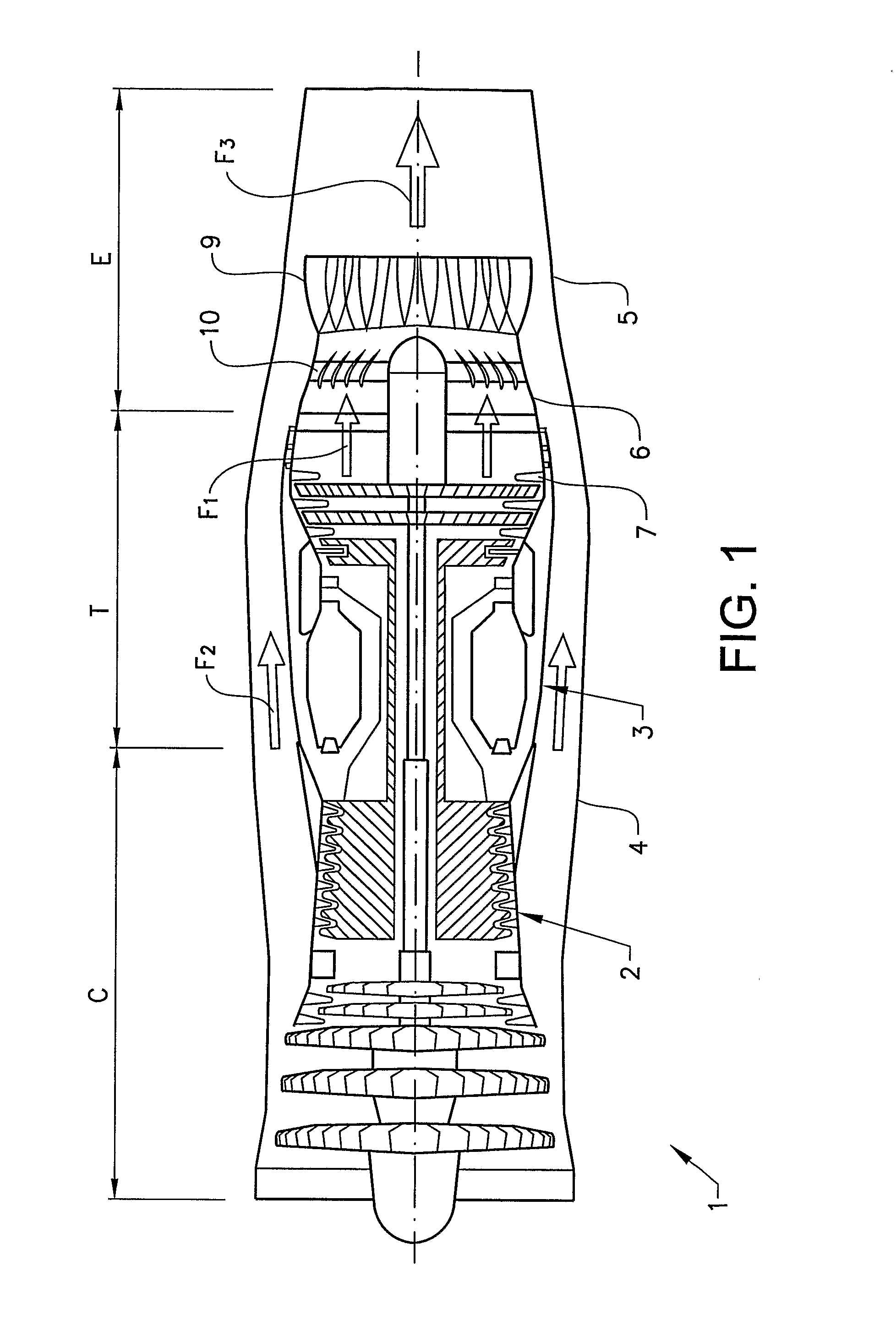
[0054]FIG. 1 shows a schematic cross-section of a gas turbine engine 1 according to the invention. The turbofan engine 1 comprises a compressor and fan section C, a combustor section and turbine section T and an exhaust section E. The compressor and fan section C is enclosed by a compressor shroud 2, while the combustor section and turbine section T is enclosed by a turbine shroud 3. The turbine shroud 3 is arranged to contain a central core flow F-i. A fan flow F2 that passes through a first part of the fan section is arranged to bypass the combustor and turbine section T by flowing through a fan flow shroud 4 surrounding the turbine shroud 3. The core flow Fi and fan flow F2 is passed into an exhaust shroud 5, where they are mixed and exit the engine as an exhaust flow F3. The exhaust section E is enclosed by an exhaust case 5. At the end of the turbine section T the core flow Fi is contained by an outer wall formed by an inner exhaust nozzle 6 attached to the end of the turbine s...


PUM


Abstract

A masking arrangement for a gas turbine engine includes a plurality of annular elements arranged overlapping one another when these are viewed in an axial direction so as to mask at least a substantial portion of any interior hot and rotating gas turbine engine part at an aft end of the gas turbine engine from rear view when the masking arrangement is applied downstream the interior part in the gas turbine engine.

Description

BACKGROUND AND SUMMARY[0001]The invention relates to a masking arrangement for a gas turbine engine, in particular for masking off an exhaust duct of the gas turbine engine in order to avoid detection and especially to reduce the infra-red and / or radar signature of said gas turbine engine. This involves reducing the infra-red radiation of any rotating and hot parts of the gas turbine, so that they are not visible through an exhaust duct extending downstream from the turbine, and preferably to eliminate or reduce radar reflecting surfaces in said exhaust duct.[0002]It has long been realized that it may be quite desirable under certain circumstances to minimize visibility of the turbine of a gas turbine engine or, in other words, to minimize direct radiation from the hot pans of the engine out the exhaust pipe or jet nozzle of such an engine.[0003]One reason for this is that rotating and hot parts of the gas turbine used in jet engines can be observed from a rear view through the exha...

Claims


Application Information

Patent Timeline
IPC IPC(8): F02K1/82
CPCF02K1/825F02K3/10Y02T50/671Y02T50/60
Inventor STROM, LINDAMARTENSSON, HANSLARSSON, JONASANDERSSON, LENA
Owner GKN AEROSPACE SWEDEN AB
Why Eureka
Try Eureka