Refrigerant system with cascaded circuits and performance enhancement features

a cascaded circuit and refrigerant technology, applied in the field of cascaded refrigerant systems, can solve the problems of refrigerant systems utilizing cosub>2/sub>as a refrigerant that does not always operate at the efficiency level of traditional refrigerant systems, and none of the above-referenced enhancement features have been incorporated into the cascaded refrigerant systems to achieve the effect of enhancing the operation of the cascaded r

a cascaded circuit and refrigerant technology, applied in the field of cascaded refrigerant systems, can solve the problems of refrigerant systems utilizing cosub>2/sub>as a refrigerant that does not always operate at the efficiency level of traditional refrigerant systems, and none of the above-referenced enhancement features have been incorporated into the cascaded refrigerant systems to achieve the effect of enhancing the operation of the cascaded r

US20100147006A1Inactive Publication Date: 2010-06-17CARRIER CORP

Image

  • Refrigerant system with cascaded circuits and performance enhancement features
  • Refrigerant system with cascaded circuits and performance enhancement features
  • Refrigerant system with cascaded circuits and performance enhancement features

Examples


Embodiment Construction

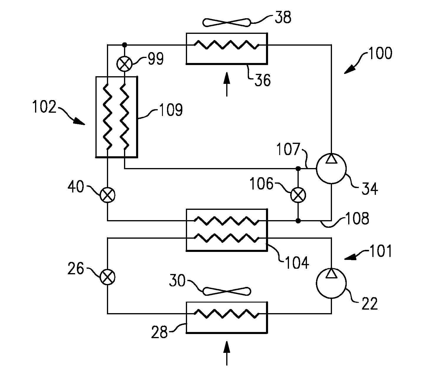
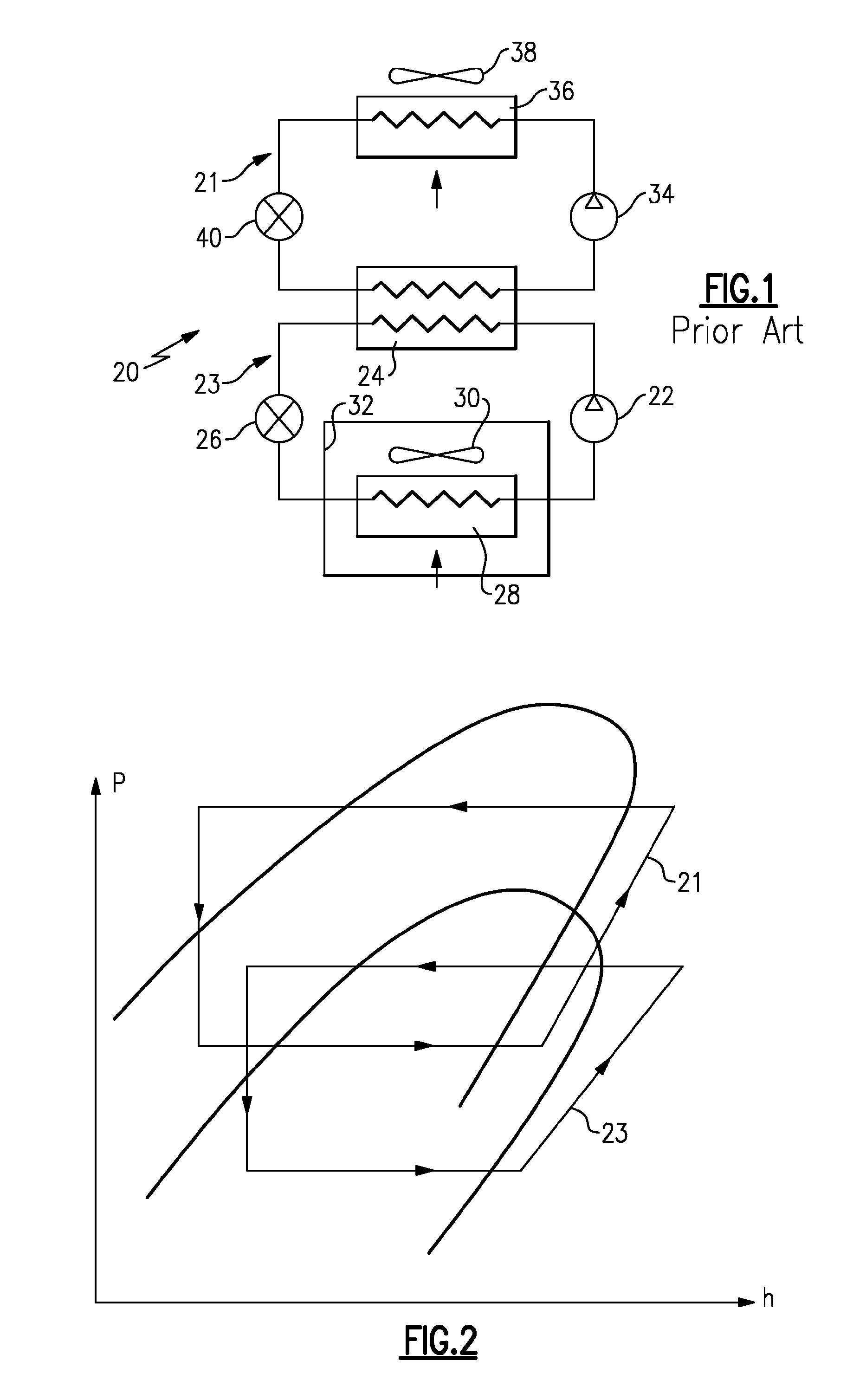
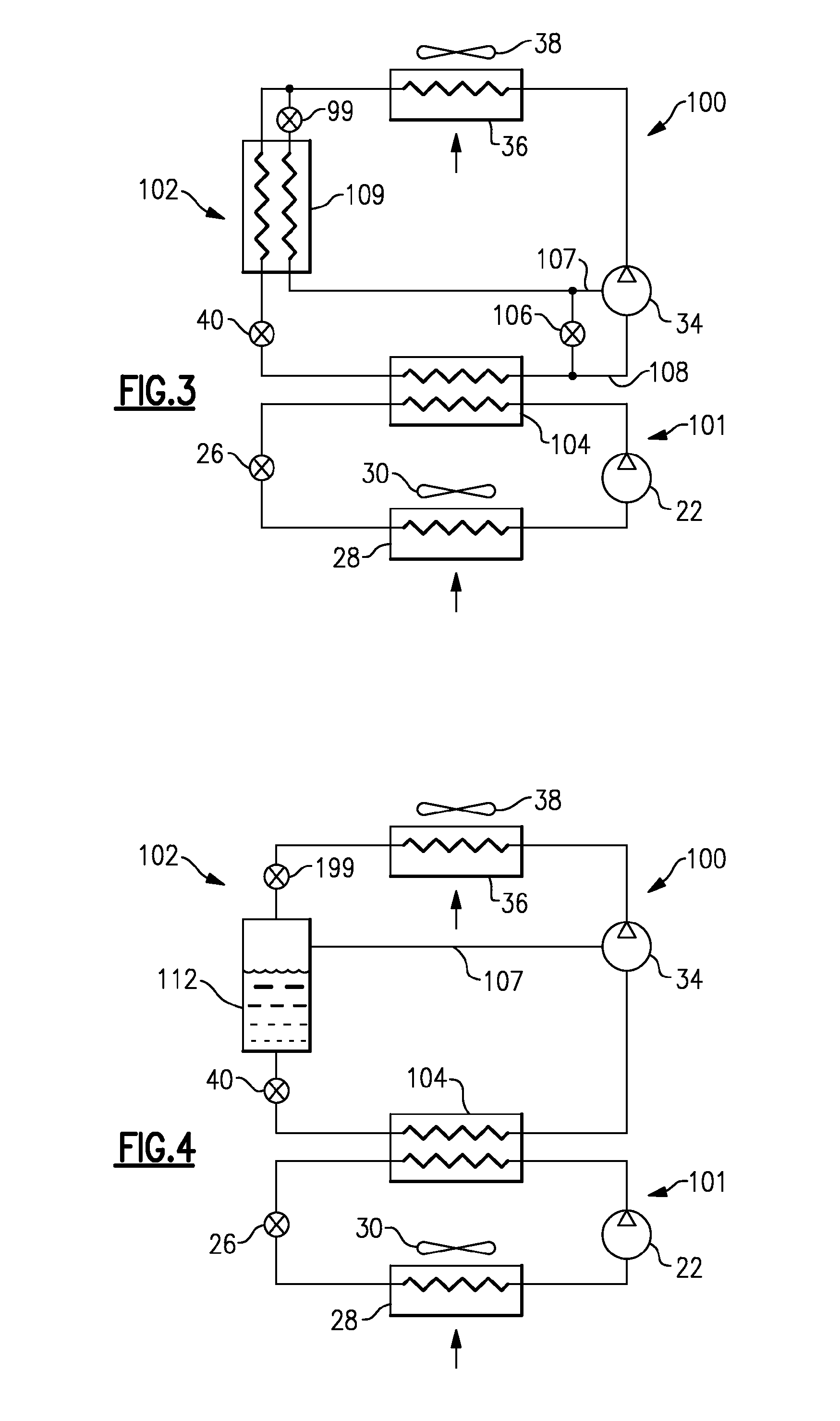
[0022]FIG. 1 shows a prior art refrigerant system 20 incorporating two cascaded circuits 21 and 23. A lower stage circuit 23 includes a compressor 22 delivering a compressed refrigerant into a refrigerant-to-refrigerant heat exchanger 24. Heat exchanger 24 is preferably positioned outside of an environment 32 to be conditioned. Refrigerant passes from the heat exchanger 24 through an expansion device 26, and to an indoor heat exchanger 28. As known, a fan 30 blows air over external surfaces of the indoor heat exchanger 28 and delivers that conditioned air into the environment 32. The lower stage circuit 23 would normally be charged with a refrigerant that would operate in a subcritical region. One such refrigerant that can be used for this circuit would be CO2 refrigerant that, while in the lower cascaded circuit, would still be in the subcritical region. If this same CO2 refrigerant would have been used in the upper cascaded circuit, it is likely to operate at transcritical regime....


PUM


Abstract

An improved refrigerant system incorporates at least two circuits arranged in a cascaded relationship. Preferably, the upper circuit utilizes a hydrocarbon refrigerant and preferably the lower circuit utilizes CO2 refrigerant. Preferably, the CO2 circuit mainly operates in a subcritical region. To improve the efficiency and capacity control of the cascaded refrigerant system, at least one of the circuits is equipped with performance enhancement features such as, for example, an economized function provided by a flash tank or economizer heat exchanger. Additional enhancement features can also include a liquid-suction heat exchanger and bypass function.

Description

BACKGROUND OF THE INVENTION[0001]This application relates to refrigerant systems with at least two cascaded circuits, and more particularly, to cascade refrigerant systems with performance enhancement features.[0002]For instance, two distinct refrigerants can be utilized in each of the two circuits, with a hydrocarbon refrigerant utilized only in the upper stage circuit and another refrigerant utilized in the lower stage circuit. The hydrocarbon type of refrigerant can be, for example, propane or isobutene refrigerant. Since the upper stage circuit can be located outside of the enclosed conditioned compartment, it would offer an advantage of locating the flammable refrigerant also outside of the enclosed space, which would mitigate flammability concerns of these refrigerants. By utilizing the two cascaded circuits, the amount of charge in the upper stage circuit would be substantially reduced as compared to a single circuit refrigerant system. Since the amount of charge in the upper...

Claims


Application Information

Patent Timeline
17 Jun 2010
Publication
US20100147006A1
IPC
F25B7/00; F25B41/00; F25B1/10
CPC
F25B1/10; F25B7/00; F25B2400/13; F25B2400/12; F25B2309/06
Inventors
TARAS, MICHAEL F.; LIFSON, ALEXANDER