Hybrid drive train of a motor vehicle

a hybrid drive and motor vehicle technology, applied in the direction of gearing control, gear lubrication/cooling, gearing elements, etc., can solve the problems of considerable effort and cost in maintenance or replacement of power electronics units, and achieve the effects of simple assembly, simplified system, and very short connection between electric machines

Inactive Publication Date: 2010-06-17
ZF FRIEDRICHSHAFEN AG
View PDF99 Cites 4 Cited by
  • Summary
  • Abstract
  • Description
  • Claims
  • Application Information

AI Technical Summary

Benefits of technology

[0015]By virtue of the concept according to the invention, of a hybrid drive train with the power electronics unit arranged under or in the transmission oil sump in the immediate vicinity of the electric machine, on the one hand the connection between the electric machine is very short, which is also advantageous in relation to electromagnetic compatibility. On the other hand there is no need for connection cables, and this results in a substantial simplification of the system comprising the electric machine and the power electronics unit. By integrating prefabricated components in order to create the multi-phase connection to the electric machine in the transmission housing and in the transmission, assembly is simplified, the number of components is reduced and the assembly time is considerably reduced.
[0016]A further advantage of the concept according to the invention is that thanks to the structural-space-neutral arrangement of the power electronics unit, no additional structural space is needed. As a result, a hybridized transmission according to the invention can be fitted as an equipment variant in a vehicle having a transmission without hybrid drive, without having for this to make modifications in the vehicle to the structure of the transmission tunnel, the length of the drive train and the flange connections to the internal combustion engine and to the cardan shaft.
[0017]Moreover, due to the arrangement of the power electronics unit under the transmission oil sump, the transmission oil acts as a coolant which can advantageously also be used for cooling the power electronics unit, so that there is no need for additional measures for cooling the power electronics unit.
[0018]Related to this, under certain operating conditions, for example during a cold start, the power loss of the power electronics unit can be used to help heat the transmission oil circuit so as to bring it up to or keep it at operating temperature. This is particularly advantageous when, during low-load phases of the internal combustion engine, the electric machine is to replace it completely.

Problems solved by technology

The solutions known from DE 10 2004 048 908 A1 and DE 10 2006 005 095 A1 have the disadvantage that maintenance, or replacement of the components of the power electronics unit, involve considerable effort and cost.

Method used


Image

  • Hybrid drive train of a motor vehicle
  • Hybrid drive train of a motor vehicle

Examples


Embodiment Construction

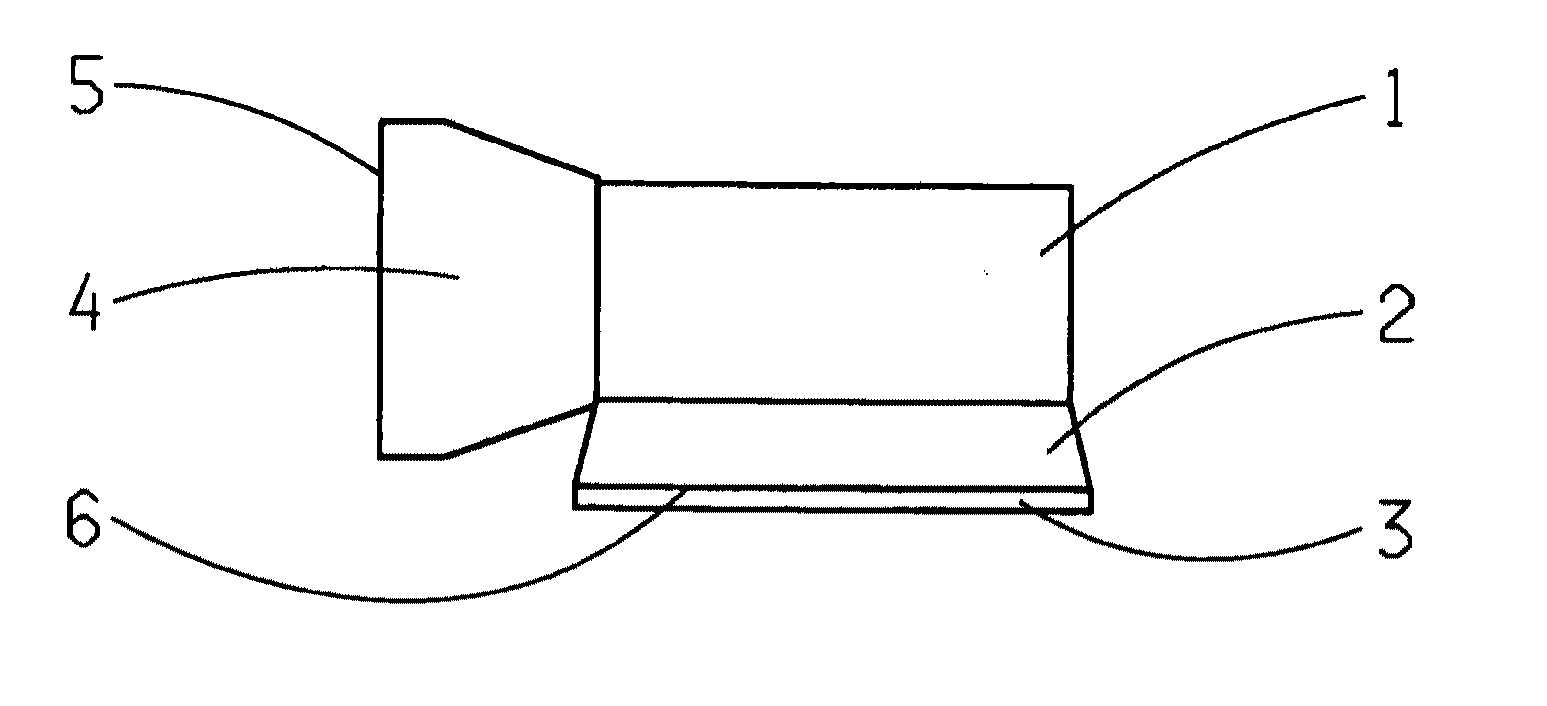
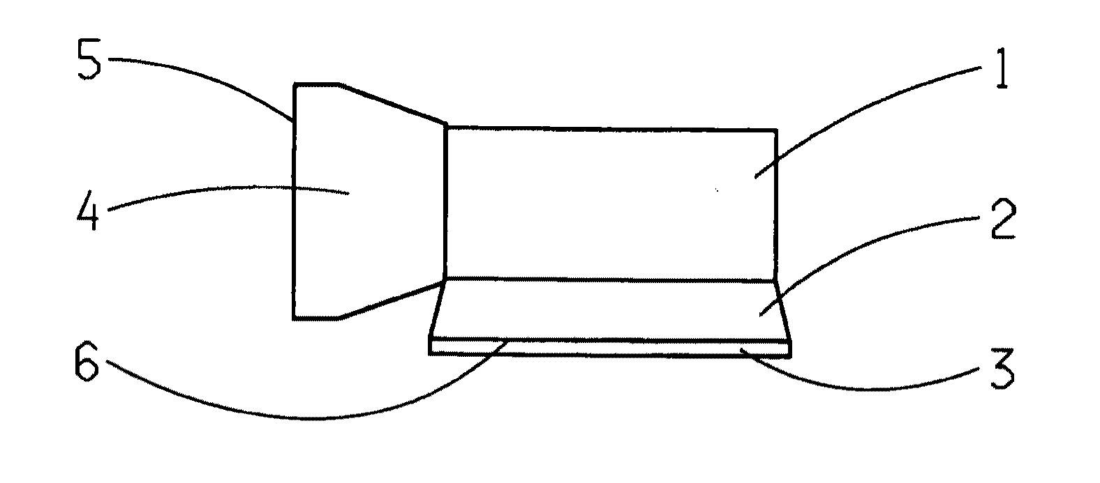
[0020]In the attached FIGURE the transmission is indexed 1, the transmission oil sump 2, the transmission bell 4 and the flange 5 to the internal combustion engine (not shown). According to the invention the structural space 3 for the power electronics unit of the at least one electric machine of the drive train is located under the transmission oil sump 2. Preferably, the area 6 between the transmission oil sump 2 and the structural space 3 for the power electronics unit is made with good thermal conductivity so that there is no need for additional measures to ensure cooling of the power electronics unit.

Indexes

[0021]1 Transmission[0022]2 Transmission oil sump[0023]3 Structural space for the power electronics unit[0024]4 Transmission bell[0025]5 Flange[0026]6 Area between the transmission oil sump 2 and the structural space for the power electronics unit


PUM


Abstract

A hybrid drive train of a motor vehicle with a transmission (1), a transmission oil sump (2) that is associated with the transmission (1), at least one electric machine, and a power electronics unit that is associated with the electric machine. A structural space (3) is provided for the power electronics unit, which is located under the transmission oil sump (2) of the transmission (1 ).

Description

[0001]This application claims priority from German patent application serial no. 10 2008 054 637.2 filed Dec. 15, 2008.FIELD OF THE INVENTION[0002]The present invention relates to a hybrid drive train of a motor vehicle.BACKGROUND OF THE INVENTION[0003]In hybrid vehicles at least one electric machine is integrated in the drive train, which is controlled by an appropriate power electronics unit comprising an inverter.[0004]From the prior art it is known to arrange the power electronics unit outside the transmission in a separate housing in the vehicle, and connect it to the electric machine by means of a three-phase or multi-phase cable.[0005]Furthermore, solutions are known in which the power electronics unit is integrated in the drive train or in the transmission.[0006]For example, from DE 10 2004 048 908 A1 a drive train for a vehicle is known, in which a converter bell is arranged between the internal combustion engine and a transmission, through which the drive shaft passes and ...

Claims


Application Information

Patent Timeline
Patent Type & Authority Applications(United States)
IPC IPC(8): F16H57/02F16H57/04
CPCF16H57/02F16H57/0452F16H57/0476Y10T74/2186F16H2057/02043Y10T74/2189F16H2057/02026
Inventor SCHOEN, WOLFGANG
Owner ZF FRIEDRICHSHAFEN AG
Why Eureka
Try Eureka