Material separation system for vacuum truck

Inactive Publication Date: 2010-06-17
BAZIUK SLAWKO MORRIS
View PDF17 Cites 22 Cited by
  • Summary
  • Abstract
  • Description
  • Claims
  • Application Information

AI Technical Summary

Benefits of technology

[0011]It is one object of the invention to provide an improved vacuum truck where there is provided a separation system within a transportation and storage tank to remove liquid content from solids content so as to allow the liquid to be returned and to increase the amount of available transportation area within the tank for the solids to be transported to a remote location.
[0020]a liquid pump mounted in the tank for extracting the separated liquid component from the tank to increase a storage capacity of the tank for the solids component to be collected and transported in the tank on the truck to a remote location for discharge;
[0028]Preferably the upper screening section includes a perforated screen support on the side of the curtain which is within the liquid collection area to prevent the curtain from being forced into the liquid collection area by the weight of collection of solids within the solids collection area and thus to hold the solids in the solid collection area.
[0030]The separating action is relatively crude since some solids can enter the liquid area without causing a breakdown, blockage or damage. However the intention is to extract as much water as is reasonably possible with a simple rugged system so as to increase the amount of solids contained.
[0033]Preferably there is provided a back-stop to prevent pivotal movement of the bottom wall portion or door in the reverse direction into the liquid collection area caused by the weight of solids collected in the solids collection area and resting against the door.
[0047]a liquid pump mounted in the tank for extracting the separated liquid component from the tank to increase a storage capacity of the tank for the solids component to be collected and transported in the tank on the truck to a remote location for discharge;

Problems solved by technology

One problem which arises with vacuum trucks of this type is that it is desirable to increase as far as possible the amount of solids which can be collected so as to transport as much as possible of the material which must be removed while returning liquid to the area being cleaned.

Method used


Image

  • Material separation system for vacuum truck
  • Material separation system for vacuum truck
  • Material separation system for vacuum truck

Examples


Embodiment Construction

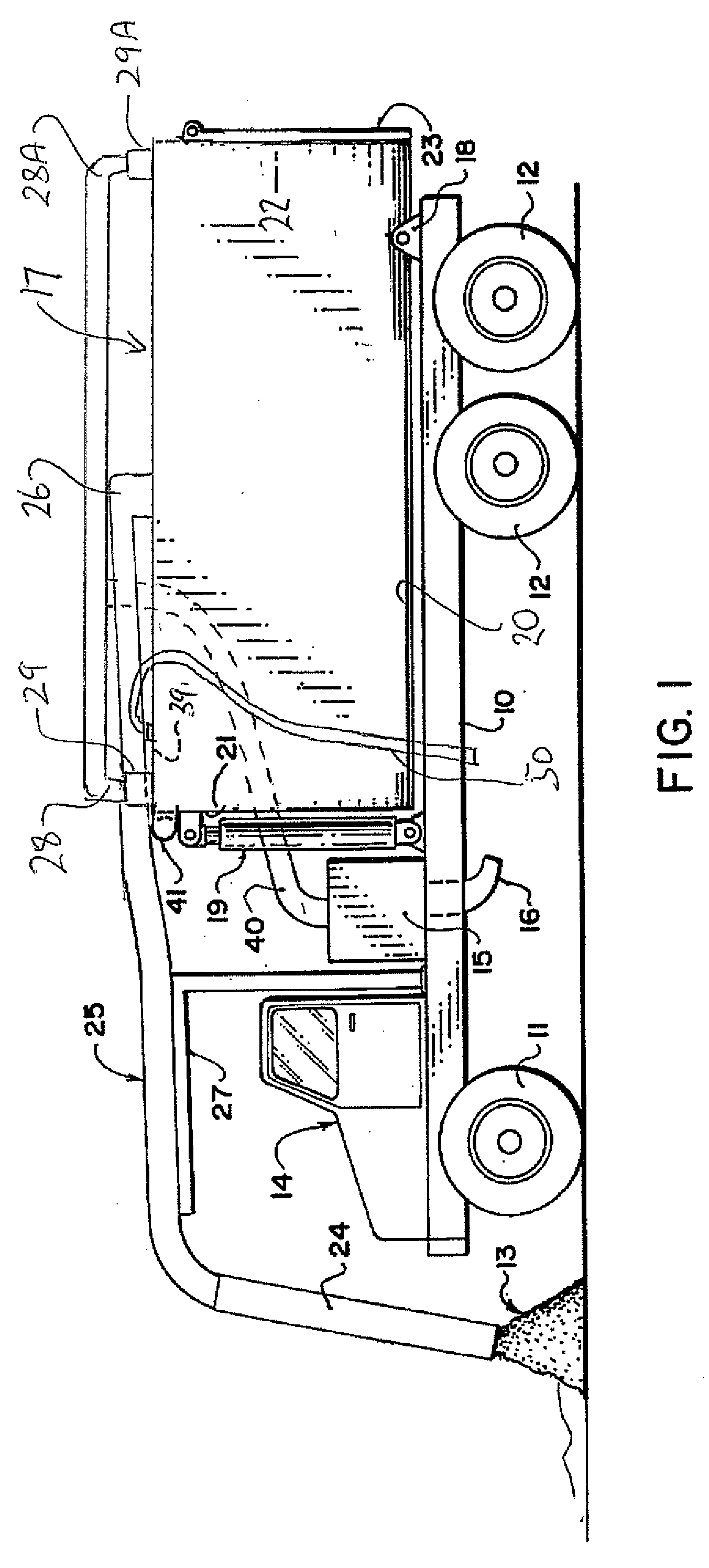
[0058]The vacuum truck of FIG. 1 comprises a truck frame 10 mounted on ground wheels 11 and 12 for movement across the ground for transporting the vacuum system from place to place for effecting excavation or extraction of materials 13 from a location to be removed. The materials commonly include a quantity of solids and liquid. Typically the vacuum truck is used to clear a blockage in a drain or culvert and hence it is necessary to remove both solid material 13 and liquid, generally water 13A, surrounding or mixed with the solids.

[0059]The frame of the truck including a cab 14 and drive systems is entirely conventional and therefore will not be described in detail herein. The truck carries a vacuum pump 15 again of a conventional nature of the type which generates a high level of vacuum and high air throughput. Such pumps are well-known and are conventionally available and include a discharge duct 16 for disposal.

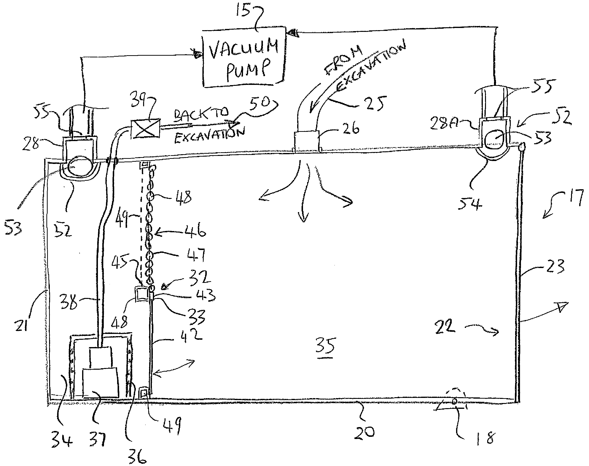
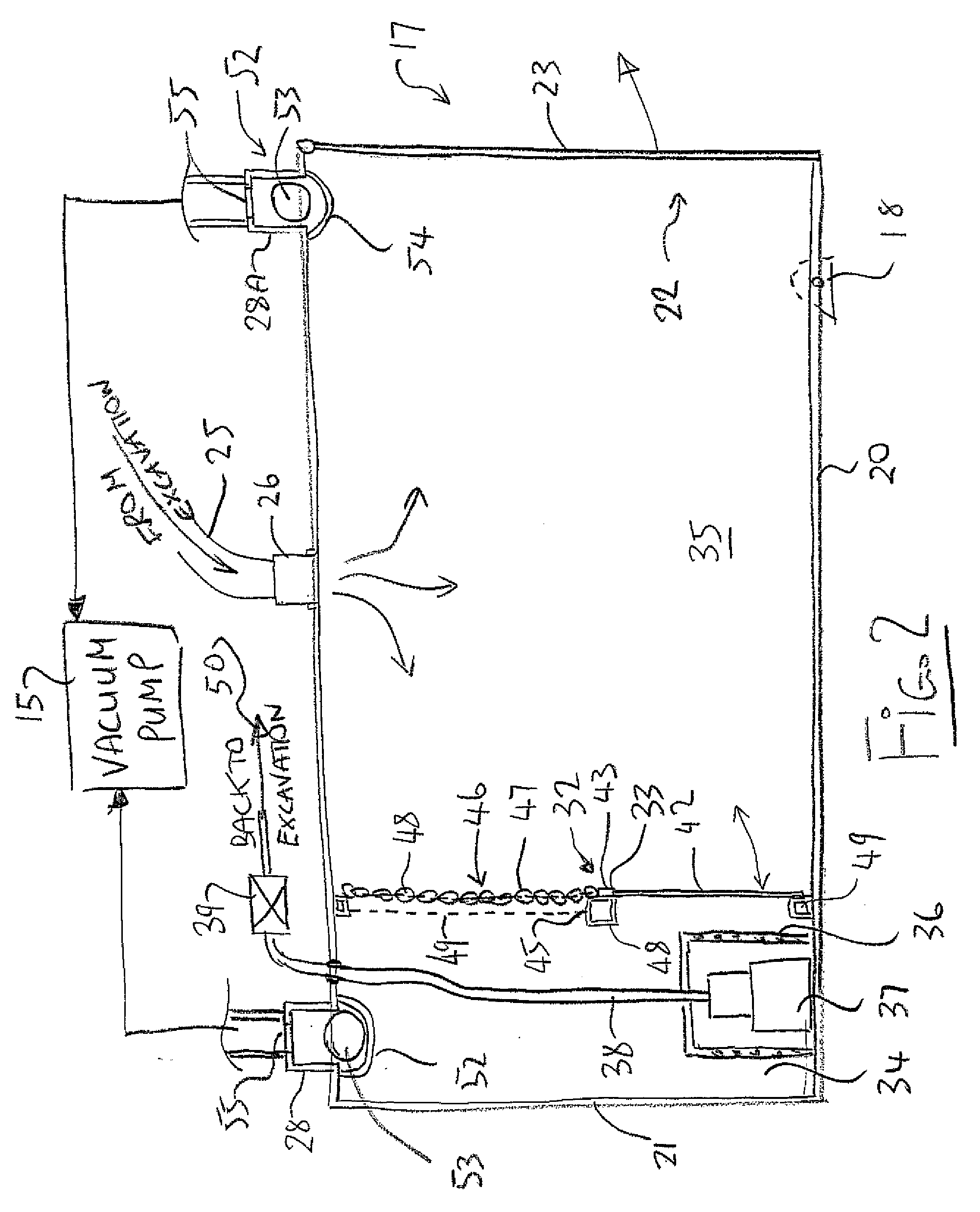
[0060]The system further includes a material storage tank and separat...


PUM

PropertyMeasurementUnit
areaaaaaaaaaaa
side lengthsaaaaaaaaaa
lengthsaaaaaaaaaa

Abstract

A vacuum truck has a cylindrical tank which can be pivoted to discharge through a rear door is arranged for transporting collected solids while liquid is extracted and returned. Two tank extraction outlets in the top wall at the front and rear are connected to the vacuum pump and each includes a float valve ball contained in a receptacle above the top wall as to allow the tank to be filled to the top wall. For separating the materials into liquid which is pumped away and solids for transportation, the tank includes a generally upstanding dividing wall across the tank having a bottom wall portion, which can pivot away as the tank is tilted, and has a top edge defining a weir over which liquid can flow into the liquid collection area, and an upper screening section defined by a support screen and a hanging chain curtain in front of the screen.

Description

[0001]This invention relates to a vacuum truck for vacuum extraction to a storage tank of liquids and solids from an area to be cleaned, which uses a separation system within the storage tank to remove liquid content from solids content so as to allow the liquid to be returned to the area and to increase the amount of available transportation area within the tank for the solids to be transported to a remote location.BACKGROUND OF THE INVENTION[0002]Vacuum trucks are well-known and widely used for excavation or extraction of particulate material by vacuum from an area to be cleared, with the material collected being transported through a vacuum hose into a storage tank from which the material is separated from the air before the air enters the vacuum pump.[0003]Such vacuum trucks are commonly used for clearing pipes and other areas where a collection of solid material needs to be extracted from an area containing water. Thus a blocked sewer or drainage pipe contains water which can b...

Claims


Application Information

Patent Timeline
Patent Type & Authority Applications(United States)
IPC IPC(8): C02F1/40B01D35/157C02F103/06
CPCE03F7/10B60P3/2245
Inventor BAZIUK, SLAWKO MORRIS
Owner BAZIUK SLAWKO MORRIS
Why Eureka
Try Eureka