Water saving valve device

Inactive Publication Date: 2010-06-17
HO YEONG JEONG
View PDF5 Cites 7 Cited by
  • Summary
  • Abstract
  • Description
  • Claims
  • Application Information

AI Technical Summary

Benefits of technology

[0013]Accordingly, the present invention has been made keeping in mind the above problems occurring in the prior art, and an object of the present invention is to provide a water saving valve device, which does not use a solenoid and manually moves an actuating rod up and

Problems solved by technology

However, since the conventional water saving valve device uses the solenoid, the malfunction of the valve device frequently occurs at the time of performing the switching operation in response to an electric signal.
Further, the solenoid increases the volume of the valve

Method used


Image

  • Water saving valve device
  • Water saving valve device
  • Water saving valve device

Examples


Embodiment Construction

[0032]Hereinafter, the construction of a water saving valve device according to the preferred embodiment of the present invention will be described in detail with reference to the accompanying drawings.

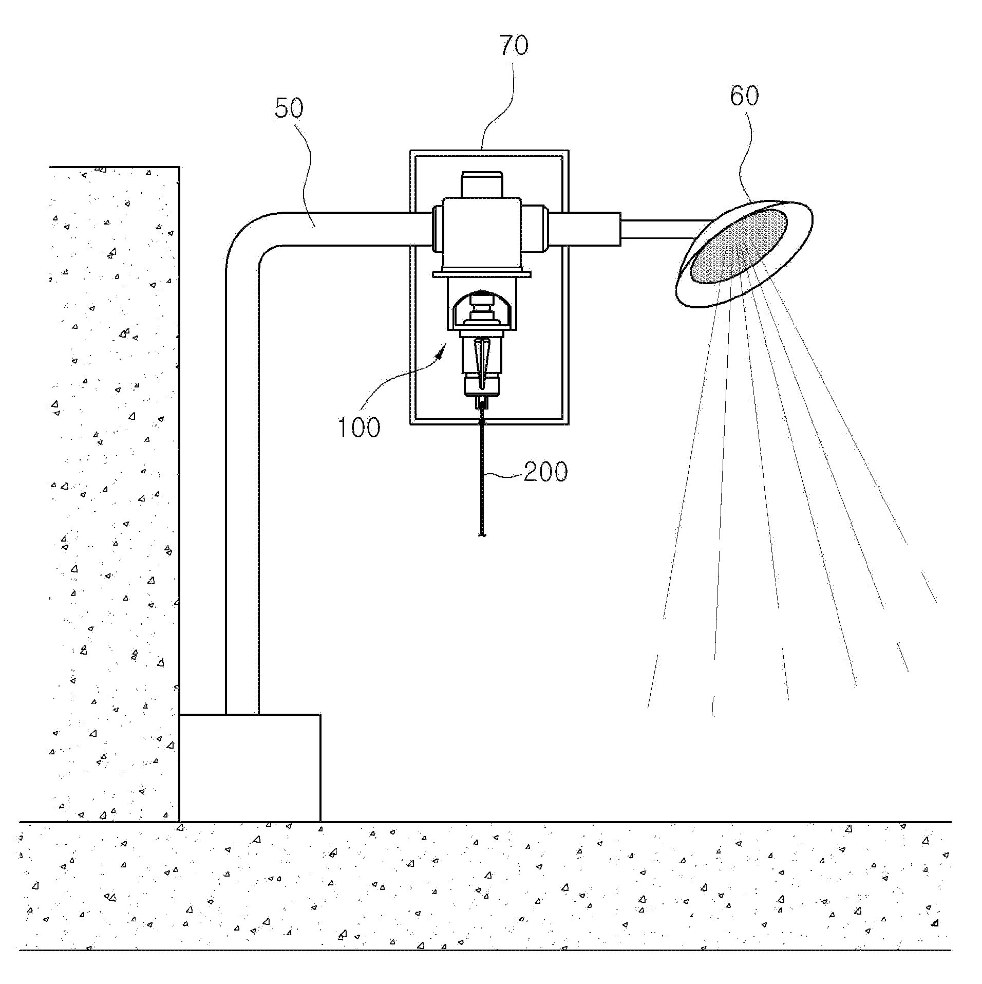
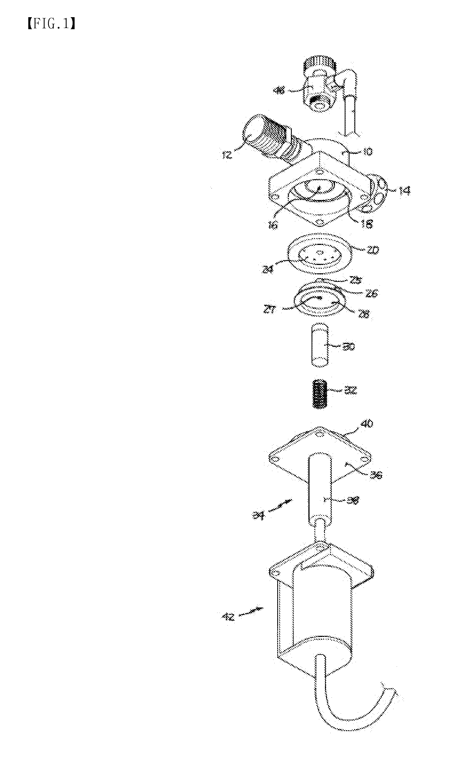
[0033]FIG. 3 illustrates a water saving valve device according to the present invention which is installed to a shower, and FIG. 4 is an exploded perspective view illustrating the water saving valve device according to the present invention.

[0034]As shown in FIG. 3, the water saving valve device according to the present invention is provided between a water pipe 50 connected to a water supply pipe and a shower head 60 to temporarily cut off the supply of water to the shower head 60 as necessary. Preferably, the water saving valve device is surrounded by an additional casing, as shown in the drawing.

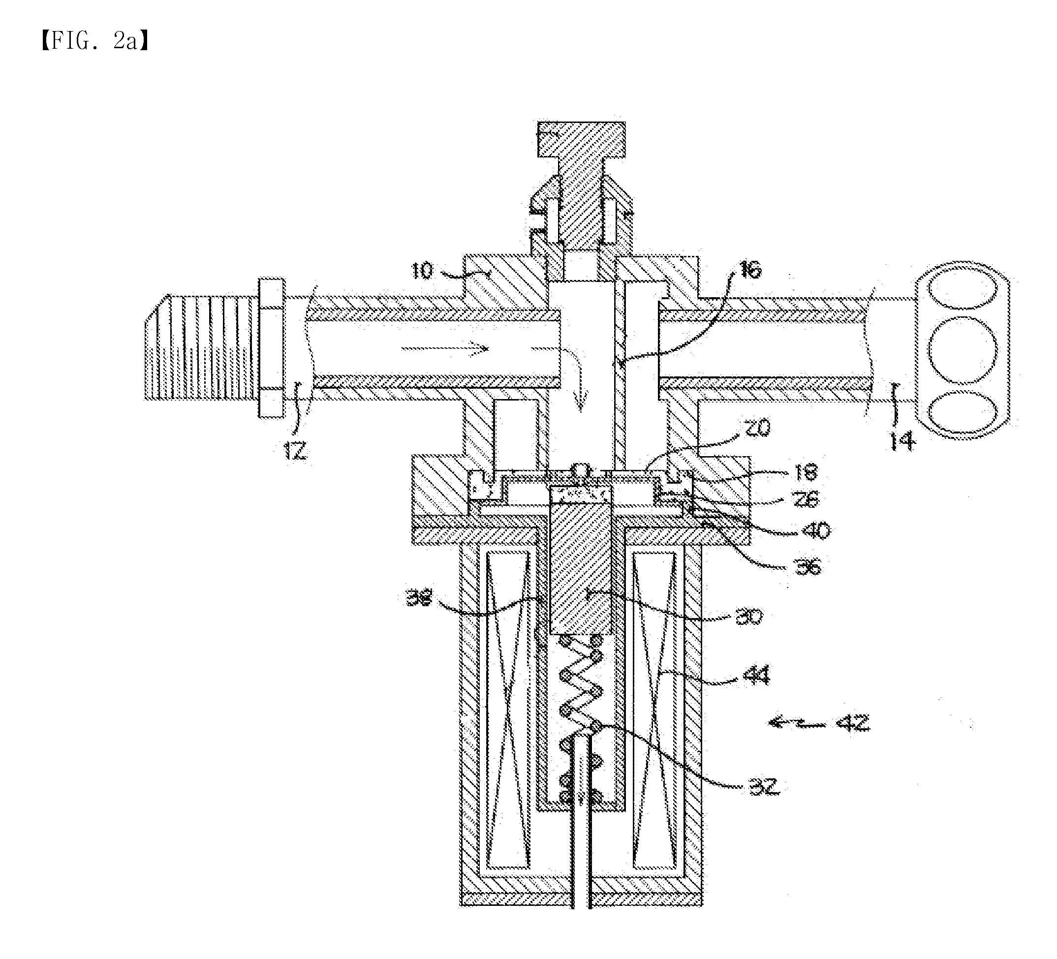
[0035]The upper construction of the water saving valve device according to the present invention remains the same as that of the conventional solenoid valve which has been described above. ...


PUM


Abstract

Disclosed herein is a water saving valve device having a valve body, a coupling unit, a spring, an actuating rod, a push plate, and a packing. A manual manipulating unit is coupled to the coupling unit to manually move the actuating rod up and down, and includes a lower body, a slide bar, a spring, and a locking piece. The lower body is coupled to the coupling unit and has a vertical pipe on its lower portion. The slide bar has on its upper end a magnet, thus vertically moving the actuating rod by magnetic force. The spring is fitted over the lower portion of the slide bar. The upper end of the locking piece is alternately stopped by first and second locking holes when the slide bar moves up and down, and the lower end is supported by the outer circumference of the vertical pipe.

Description

[0001]This application claims benefit of Serial No. 10-2008-0127689, filed 16 Dec. 2008 in South Korea and which application is incorporated herein by reference. To the extent appropriate, a claim of priority is made the above disclosed application.BACKGROUND OF THE INVENTION[0002]1. Field of the Invention[0003]The present invention relates generally to water saving valve devices and, more particularly, to a water saving valve device which is installed at a position between a water pipe and a shower head and is manually opened or closed when necessary, thus controlling the discharge of water from the shower head, therefore saving water.[0004]2. Description of the Related Art[0005]Generally, a home bathroom, public bath, or swimming place is provided with a shower facility. A shower is installed in the shower facility. The shower includes a water pipe which is connected to a water supply pipe, and a shower head which sprays water supplied through the water pipe. A valve or tap is cou...

Claims


Application Information

Patent Timeline
IPC IPC(8): E03C1/02
CPCE03C1/055A47K3/28
Inventor HO-YEONG, JEONG
Owner HO YEONG JEONG
Why Eureka
Try Eureka