Brushless motor

a brushless motor and brushless technology, applied in the direction of dynamo-electric machines, electrical equipment, magnetic circuit shapes/forms/construction, etc., can solve the problems of increased manufacturing costs, limited reduction of the thickness of the magnet, and high price of strong permanent magnets such as neodymium magnets, so as to reduce the fluctuation of the magnetic balance and high performance

Active Publication Date: 2010-06-17
DENSO CORP
View PDF4 Cites 70 Cited by
  • Summary
  • Abstract
  • Description
  • Claims
  • Application Information

AI Technical Summary

Benefits of technology

[0015]A first objective of the present invention is to provide a brushless motor that ...

Problems solved by technology

However, strong permanent magnets such as neodymium magnets are expensive, and there are limitations in reducing the thickness of the magnets.
Thus, the manufacturing costs are increased when manufacturing a multipole motor (for example, an 8-pole 12-slot motor) using the strong permanent magnets as disclosed in Japanese Laid-Open Patent Publication No. 2008-113531.
This causes fluctuation of the magnetic bal...

Method used


Image

  • Brushless motor
  • Brushless motor
  • Brushless motor

Examples


first embodiment

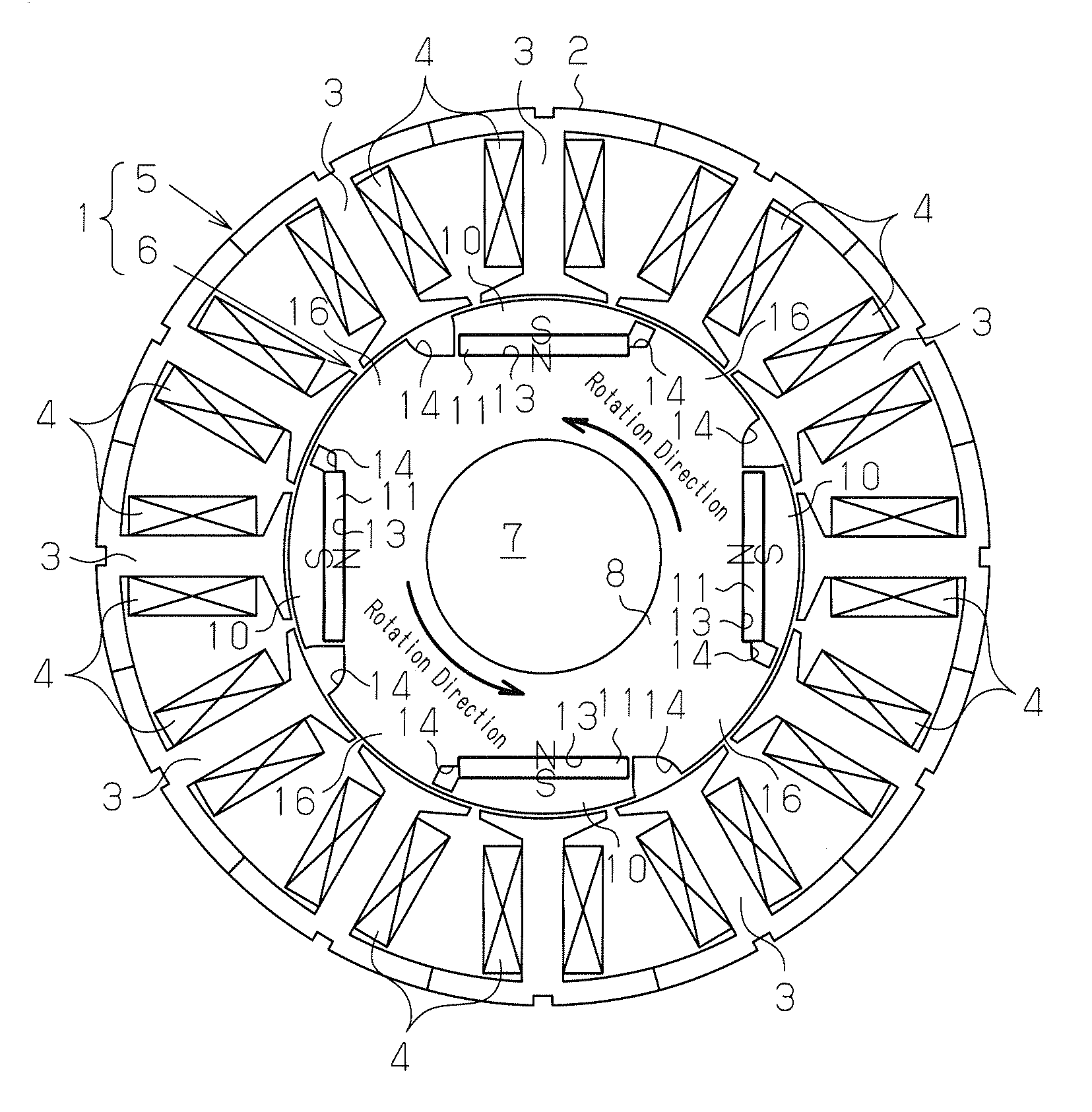
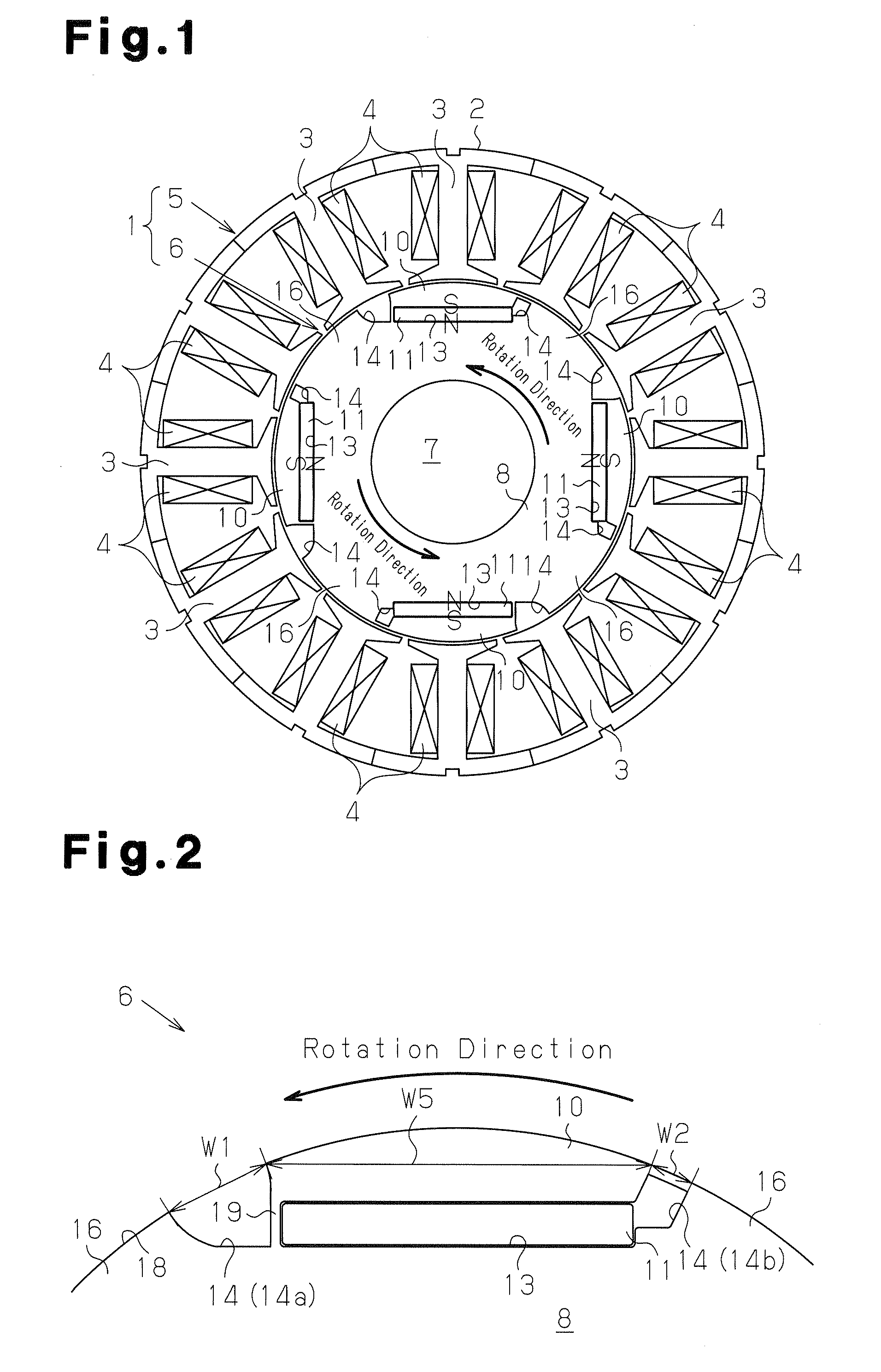
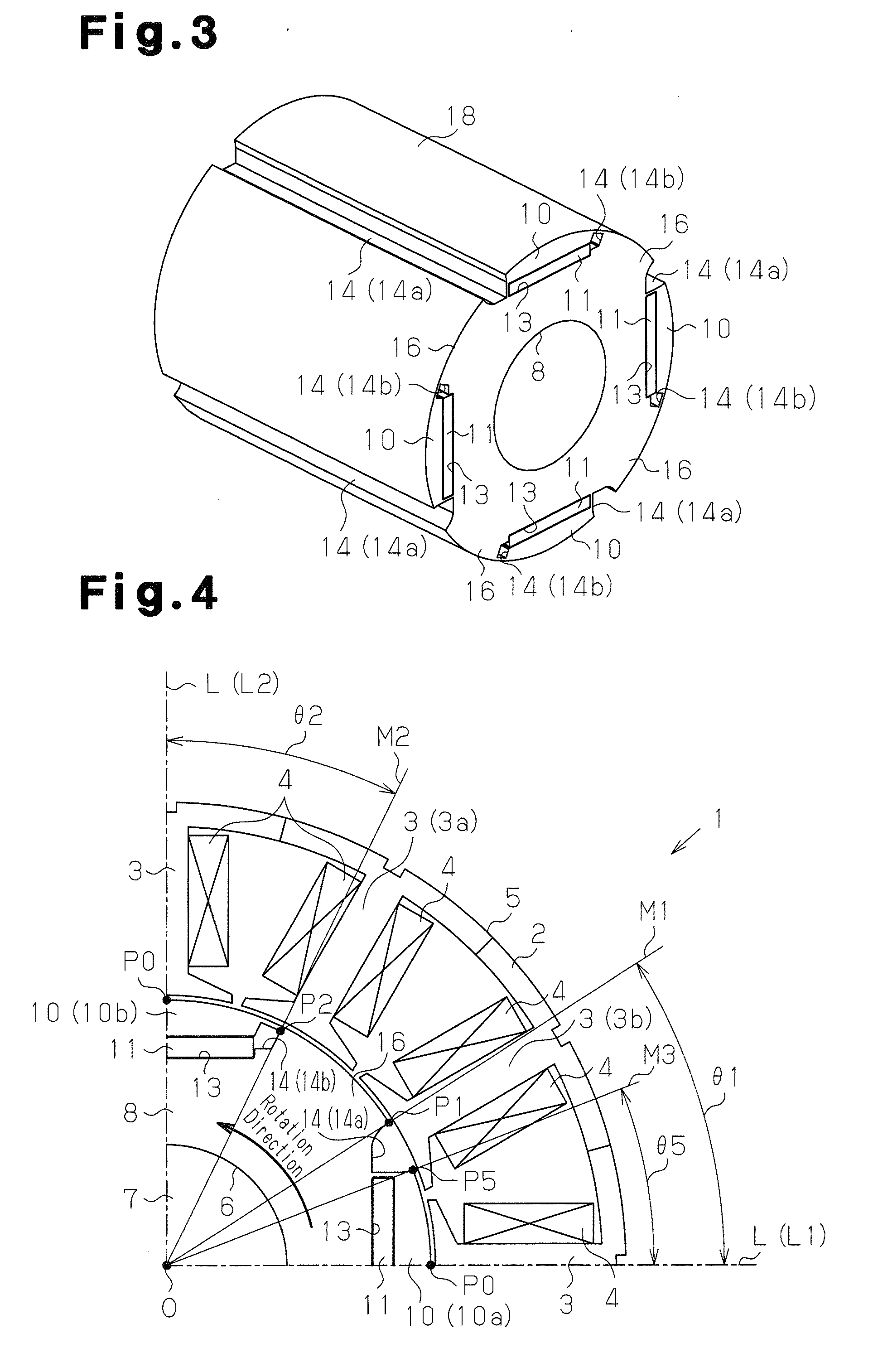
[0069]A brushless motor (IPM motor) 1 including an embedded permanent magnet rotor 6 according to the present invention will now be described with reference to FIGS. 1 to 9.

[0070]As shown in FIG. 1, the brushless motor 1 of the present embodiment includes a stator 5 and the rotor 6. The stator 5 includes an annular portion 2, teeth 3, which extend radially inward from the annular portion 2, and coils 4, which are wound around the teeth 3.

[0071]In the present embodiment, the stator 5 includes twelve teeth 3, and the stator 5 therefore has twelve slots. Three-phase alternating current is supplied to the coils 4.

[0072]The rotor 6 includes a rotary shaft 7 and a columnar rotor core 8, which is secured to the rotary shaft 7. The rotary shaft 7 is supported by non-illustrated bearings. The rotor 6 is arranged radially inward of the stator 5 while being surrounded by the teeth 3, and is freely rotatable. Magnetic pole portions 10, which face the teeth 3 surrounding the rotor 6, are provide...

second embodiment

[0106]A brushless motor (IPM motor) 1B will be described with reference to FIGS. 10 and 11.

[0107]FIG. 10 shows part of a cross-section of the motor 1B according to the second embodiment. FIG. 10 shows an iron core portion 61 of a rotor 60 of the second embodiment. A circumferential center portion of an outer side surface 61x of the iron core portion 61 is located on an imaginary reference circumferential surface C (for example, the radius from the rotor center O is 22 mm) formed by connecting outer side surfaces 10X of all the magnetic pole portions 10. The outer side surface 61x is curved such that it separates radially inward from the circumferential surface C as the distance from the circumferential ends decreases. That is, the outer side surface 61x of the iron core portion 61 has a greater curvature than the circumferential surface C. In other words, the outer side surface 61x has a small curvature radius so that, toward the end portions from the circumferential center portion...

third embodiment

[0130]A brushless motor 1C according to the present invention will now be described with reference to FIGS. 24 to 32.

[0131]In the present embodiment, the coils 4 are formed by three phases including a U-phase, a V-phase, and a W-phase. Three phases are arranged such that forward winding and reverse winding are located side by side per each phase, such as in the order of a W-phase (forward winding), a W-phase (reverse winding), a V-phase, a V-phase, a U-phase, a Ū-phase, a W-phase, a W-phase, a V-phase, a V-phase, a Ū-phase, and a

[0132]U-phase in the clockwise direction of FIG. 24. Three-phase (U-phase, V-phase, W-phase) alternating current is supplied to the coils 4 wound around the teeth 3.

[0133]The rotor 6 of the present embodiment includes five magnetic pole portions 10 on the peripheral portion of the rotor 6.

[0134]More specifically, as shown in FIGS. 24 to 32, the magnet accommodating holes 13, which extend along the axial direction of the rotor 8, are provided in the vicinity ...


PUM


Abstract

A brushless motor including a stator having teeth and a rotor having magnetic pole portions is disclosed. The magnetic pole portions are arranged to have the same polarities as each other. The rotor includes gaps that function as magnetic resistance at circumferential ends of each of the magnetic pole portions so that an iron core portion is formed between the circumferentially adjacent magnetic pole portions. Magnetic flux of the magnetic pole portions passes through the iron core portion along the radial direction. The gaps include a first gap located on the leading end of the magnetic pole portion in the rotation direction of the rotor and a second gap located on the trailing end of the magnetic pole portion in the rotation direction of the rotor. The circumferential width of the first gap is set to be greater than the circumferential width of the second gap.

Description

BACKGROUND OF THE INVENTION[0001]The present invention relates to a brushless motor including a rotor having magnetic pole portions arranged such that all the polarities are the same, and an iron core portion, which is located between circumferentially adjacent magnetic pole portions and permits the magnetic flux of the magnetic pole portions to pass in the radial direction.[0002]In a conventional brushless motor including a rotor having magnetic pole portions formed by permanent magnets, it has been proposed to increase motor torque by increasing the number of the magnetic poles, or by forming the magnetic pole portions with strong permanent magnets.[0003]However, strong permanent magnets such as neodymium magnets are expensive, and there are limitations in reducing the thickness of the magnets. Thus, the manufacturing costs are increased when manufacturing a multipole motor (for example, an 8-pole 12-slot motor) using the strong permanent magnets as disclosed in Japanese Laid-Open...

Claims


Application Information

Patent Timeline
IPC IPC(8): H02K1/17
CPCH02K1/276H02K29/03H02K21/16H02K1/2746
Inventor TAKEMOTO, YOSHIAKIYOKOYAMA, SEIYAYAMADA, YOJIKATO, SHIGEMASA
Owner DENSO CORP
Why Eureka
Try Eureka