Optical Signal Quality Monitoring Apparatus and Method

a technology of optical signal and monitoring apparatus, which is applied in the field of optical signal quality monitoring apparatus and method, can solve the problems of insufficient resolution, inability to accurately obtain information on waveform of optical signal modulated at tens of gb/s, and difficulty in obtaining waveform information by photodetector, so as to achieve enhanced sampling efficiency and accurate information on waveform

Inactive Publication Date: 2010-06-17
ANRITSU CORP
View PDF11 Cites 4 Cited by
  • Summary
  • Abstract
  • Description
  • Claims
  • Application Information

AI Technical Summary

Benefits of technology

082]Therefore, the optical pulse having the narrow width can be used for the sampling, the sampling efficiency can be enhanced with respect to the optica...

Problems solved by technology

Therefore, in the optical signal quality monitoring apparatus, it is extremely difficult to obtain the waveform information by a photodetector directly receiving the optical signal which is modulated by a data signal having a bit rate very high as tens of Gb/s.
However, in the technique disclosed in Patent Document 2, high-frequency impedance matching i...

Method used


Image

  • Optical Signal Quality Monitoring Apparatus and Method
  • Optical Signal Quality Monitoring Apparatus and Method
  • Optical Signal Quality Monitoring Apparatus and Method

Examples


Embodiment Construction

[0089]An apparatus and a method for monitoring optical signal quality according to an embodiment of the invention will be described below with reference to the drawings.

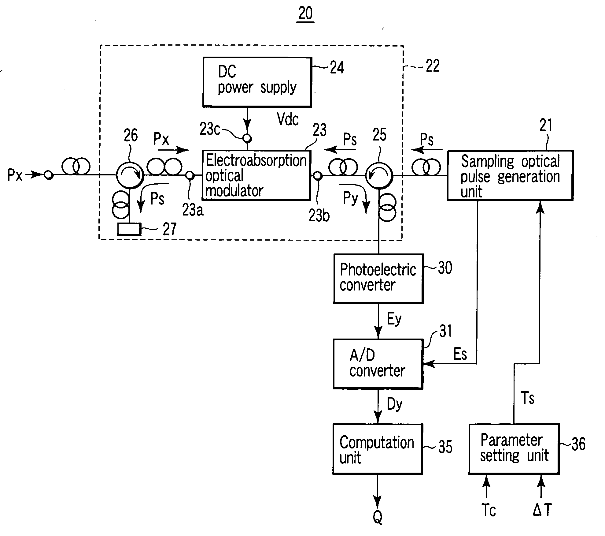
[0090]FIG. 1 is a block diagram showing configurations of an optical signal quality monitoring apparatus 20 and an optical signal quality monitoring method according to an embodiment of the invention.

[0091]A basic configuration of the optical signal quality monitoring apparatus 20 of the embodiment is as follows. The optical signal quality monitoring apparatus 20 includes a sampling optical pulse generation unit 21 which emits a sampling optical pulse Ps, the sampling optical pulse Ps having a period different from N integral multiplications of a clock period Tc of a data signal by a predetermined offset time ΔT, the data signal modulating an optical signal Px of a monitoring target; an optical sampling unit 22 which supplies an optical pulse signal Py, the optical pulse signal being obtained by sampling the optical ...


PUM


Abstract

A sampling optical pulse generation unit emits a sampling optical pulse. The sampling optical pulse has a period different from a predetermined offset time to integral multiplication of a clock period of a data signal, and the data signal modulates an optical signal of a monitoring target. An optical sampling unit performs sampling of the optical signal of the monitoring target using an electroabsorption optical modulator. The electroabsorption optical modulator has a characteristic in which an absorption index is changed with respect to light propagating through an optical path according to a level of an electric field. The optical signal of the monitoring target is input into one of two optical terminals of the electroabsorption optical modulator. The sampling optical pulse is input into another of the two optical terminals through a photocoupler. The absorption index with respect to the optical signal of the monitoring target is lowered by generating a mutual absorption saturation characteristic of the electroabsorption optical modulator when the sampling optical pulse is supplied, and the sampling of the optical signal of the monitoring target is performed to output an optical pulse signal from the other of the two optical terminals through the photocoupler.

Description

TECHNICAL FIELD[0001]The present invention relates to an optical signal quality monitoring apparatus and method, and particularly to optical signal quality monitoring apparatus and method which can correctly monitor quality of an optical signal modulated by a high-speed data signal.BACKGROUND ART[0002]In forming a network using the optical signal modulated by the data signal, it is necessary to monitor the quality of the optical signal propagating through the network with the optical signal quality monitoring apparatus.[0003]Generally, the optical signal quality monitoring apparatus obtains information on a waveform of a signal on a transmission path, and computes a value indicating the signal quality from the waveform information and supplies the computation result. Therefore, in the optical signal quality monitoring apparatus, it is extremely difficult to obtain the waveform information by a photodetector directly receiving the optical signal which is modulated by a data signal ha...

Claims


Application Information

Patent Timeline
IPC IPC(8): H04B10/08H04B10/079
CPCG01J11/00H04B10/0795
Inventor OTANI, AKIHITOTANIMOTO, TAKAO
Owner ANRITSU CORP
Why Eureka
Try Eureka