Platform seal in a turbomachine rotor, method for improving the seal between a platform and a turbomachine blade

a technology of turbomachine blades and platform seals, which is applied in the field of multi-flow, can solve the problems of high deformation, prone to twisting of the seal part, and high deformation of the downstream part of the seal, so as to reduce the frequency of replacement of the seals and improve the production of the seals

Active Publication Date: 2010-06-17
SN DETUDE & DE CONSTR DE MOTEURS DAVIATION S N E C M A
View PDF8 Cites 34 Cited by
  • Summary
  • Abstract
  • Description
  • Claims
  • Application Information

AI Technical Summary

Benefits of technology

[0008]An object of the present invention is to improve the production of the seal between the blades and the platforms of a turbomachine rotor with free interleaved platforms with the aim of reducing the frequency of replacement of the seals.

Problems solved by technology

Observing torn seals shows a tendency to twisting in the part of the seal situated downstream on the platform.
This twisting causes high deformation in a transition zone with the untwisted part of the seal.
Thus it has been found that the downstream part of the seal is liable to be pressed against the platform.

Method used


Image

  • Platform seal in a turbomachine rotor, method for improving the seal between a platform and a turbomachine blade
  • Platform seal in a turbomachine rotor, method for improving the seal between a platform and a turbomachine blade
  • Platform seal in a turbomachine rotor, method for improving the seal between a platform and a turbomachine blade

Examples


Embodiment Construction

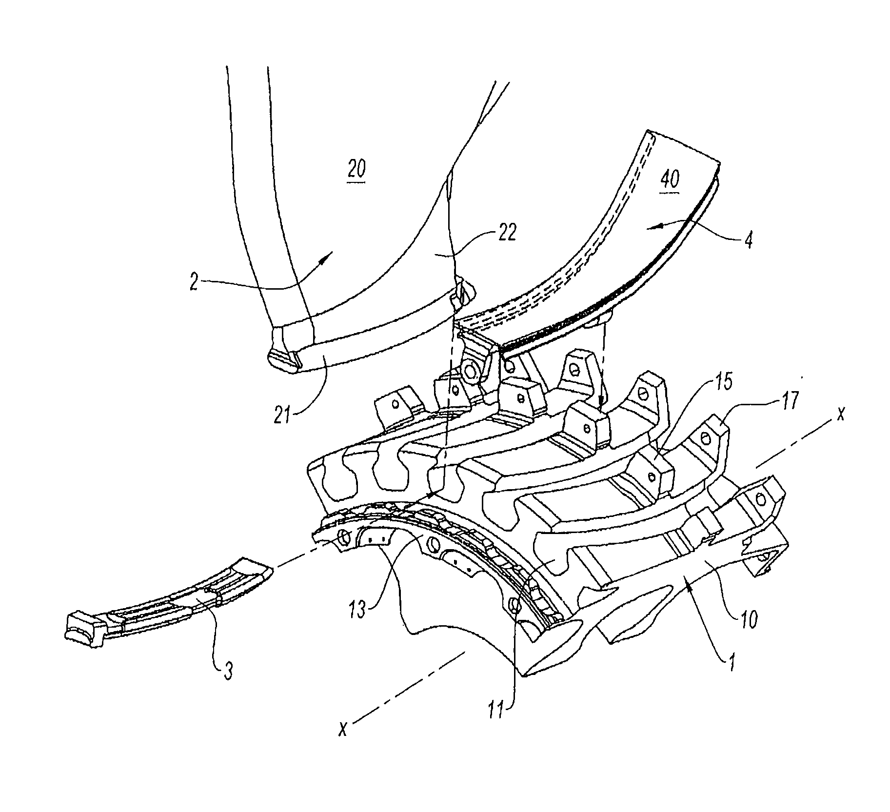
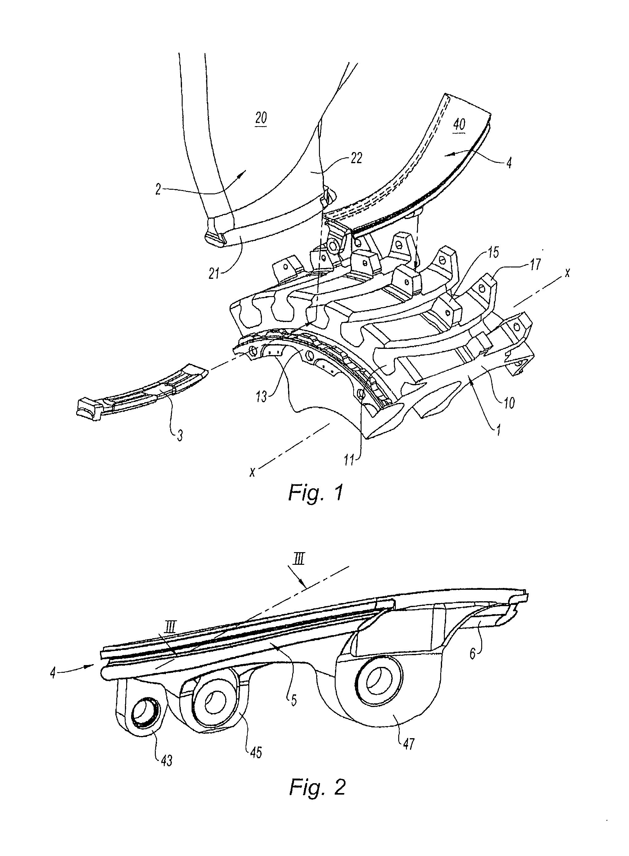
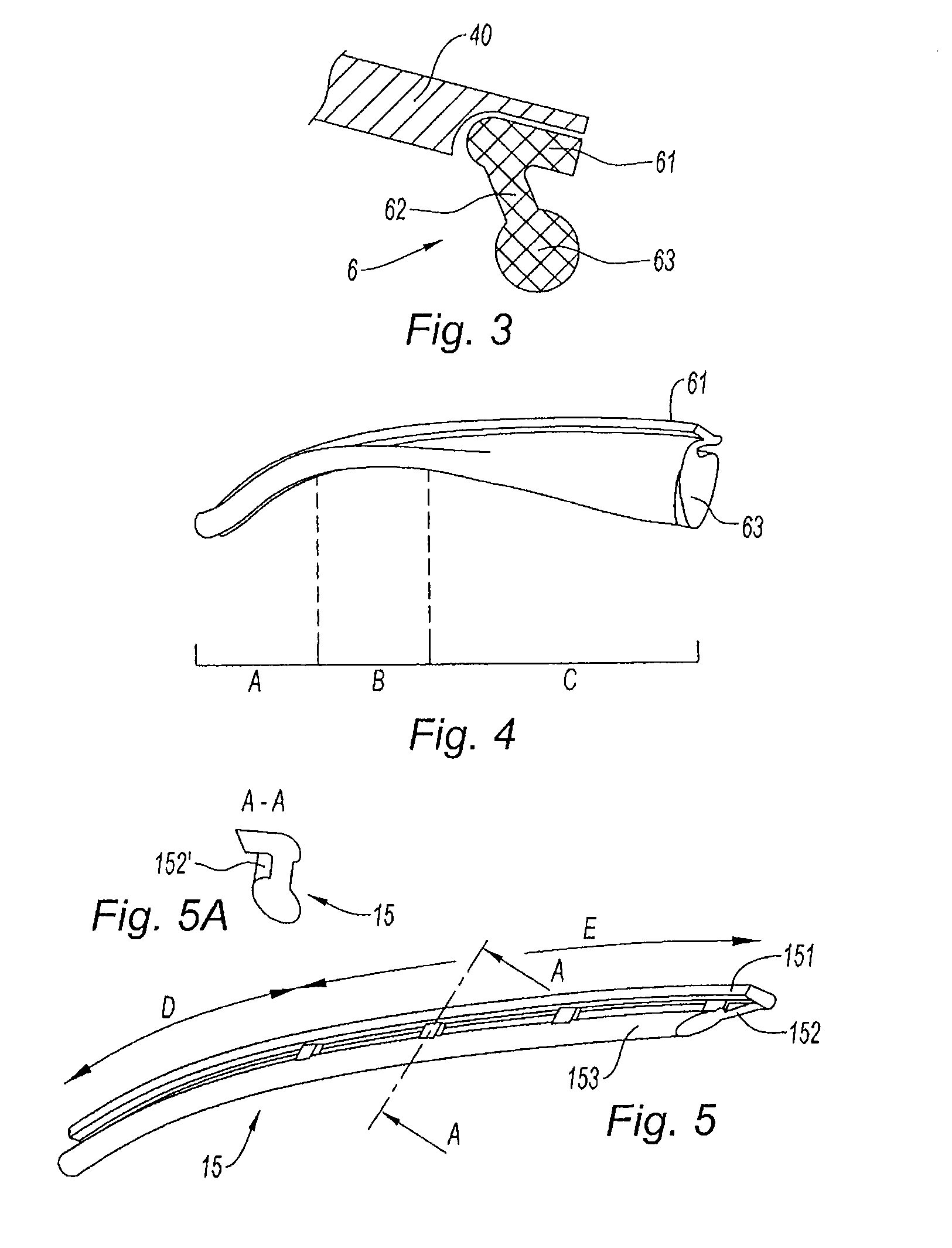
[0037]As in the prior art, the seal 15 has a section in three parts from one end to the other. It comprises an attachment part, a flexible part and a contact part.

[0038]There are distinguished in the lengthwise direction the upstream end and the downstream end; the terms upstream and downstream relate to the edges of the platform on which the seal is intended to be placed. Between these two edges the seal comprises two zones D and E. In the upstream zone D, the profile is not modified compared to the prior art, with an attachment part 151 to be glued into the corresponding groove of the platform, a flexible part 152, and a contact part 153 of circular shape here.

[0039]The length of the zone D is substantially between half and two-thirds of the length of the seal.

[0040]In the downstream zone E, the flexible part of the seal has been stiffened by at least one rib disposed crosswise, here four regularly distributed ribs. The section A-A of the seal shows that the attachment part 151 is...


PUM

PropertyMeasurementUnit
shapeaaaaaaaaaa
flexibleaaaaaaaaaa
energyaaaaaaaaaa

Abstract

An elastomer material seal for an interleaved platform between two adjacent blades in a turbomachine rotor is disclosed. The seal is of elongate shape and includes transversely a contact part, an attachment part, and a flexible part between the attachment part and the contact part. The seal is noteworthy in that it further includes a local reinforcement of the flexible part, to avoid the tearing that would result from centrifugal forces on the seal. The local reinforcement of the flexible part includes at least one transverse rib on the flexible part.

Description

BACKGROUND OF THE INVENTION[0001]The present invention concerns the field of multiflow, in particular double-flow, jet engines and more generally that of turbomachines.[0002]A double-flow jet engine comprises a gas turbine engine through which flows a flow of gas referred to as the primary flow driving a fan delivering a flow of air referred to as the secondary flow. When the fan is placed at the front of the engine, it discharges aspirated air that is separated into two concentric flows: one the primary flow, the other the secondary flow. The air of the primary flow is compressed again and then mixed with fuel in a combustion chamber to produce a high-energy gas flow that drives the downstream turbines. One of the turbines is connected by a shaft to the fan rotor, which it drives. The secondary flow in civil aircraft engines provides most of the thrust of the engine and the fan is consequently of very large diameter.[0003]The fan rotor comprises a wheel the hub of which is fastened...

Claims


Application Information

Patent Timeline
Patent Type & Authority Applications(United States)
IPC IPC(8): F01D5/30B23P15/04F16J15/10
CPCF01D5/3007F01D11/008F05D2260/941Y10T29/49321Y02T50/673F05D2240/80F05D2300/431F16J15/025Y02T50/60
Inventor FORGUE, JEAN-BERNARDREGHEZZA, PATRICK JEAN-LOUISSTOCHMIL, CAROLE
Owner SN DETUDE & DE CONSTR DE MOTEURS DAVIATION S N E C M A
Why Eureka
Try Eureka