Thermal Management Cabinet for Electronic Equipment

a technology of electronic equipment and management cabinets, which is applied in the direction of lighting and heating apparatus, casings/cabinets/drawers, and details of casings/cabinets/drawers. it can solve the problems of reliability of such fans, the need for cooling a very high percentage of the total power consumption, and the problem of affecting the cooling effect of server racks and cabinets

Inactive Publication Date: 2010-06-17
BASELAYER TECH
View PDF21 Cites 58 Cited by
  • Summary
  • Abstract
  • Description
  • Claims
  • Application Information

AI Technical Summary

Problems solved by technology

Cooling of such server racks and cabinets is a major problem, particularly as processors typically produce large amounts of heat.
It has been found that for every 1 watt of power used for Information Technology, 0.5 to 2 watts of power are used for cooling the electronic components, and thus the need for cooling uses a very high percentage of the total IT power consumption.
However, such solutions suffer from drawbacks associated with the power supply needed to power the fans, as well as reliability of such fans.
This can lead to “hot spots” in the server room, however, much of the hot air can also mix with the cool air circulating in the room.

Method used


Image

  • Thermal Management Cabinet for Electronic Equipment
  • Thermal Management Cabinet for Electronic Equipment
  • Thermal Management Cabinet for Electronic Equipment

Examples


Embodiment Construction

[0029]The exemplary embodiments of the present disclosure are described with respect to a thermal management cabinet for electronic equipment. It should be understood by one of ordinary skill in the art that the exemplary embodiments of the present disclosure can be applied to other types of thermal management systems.

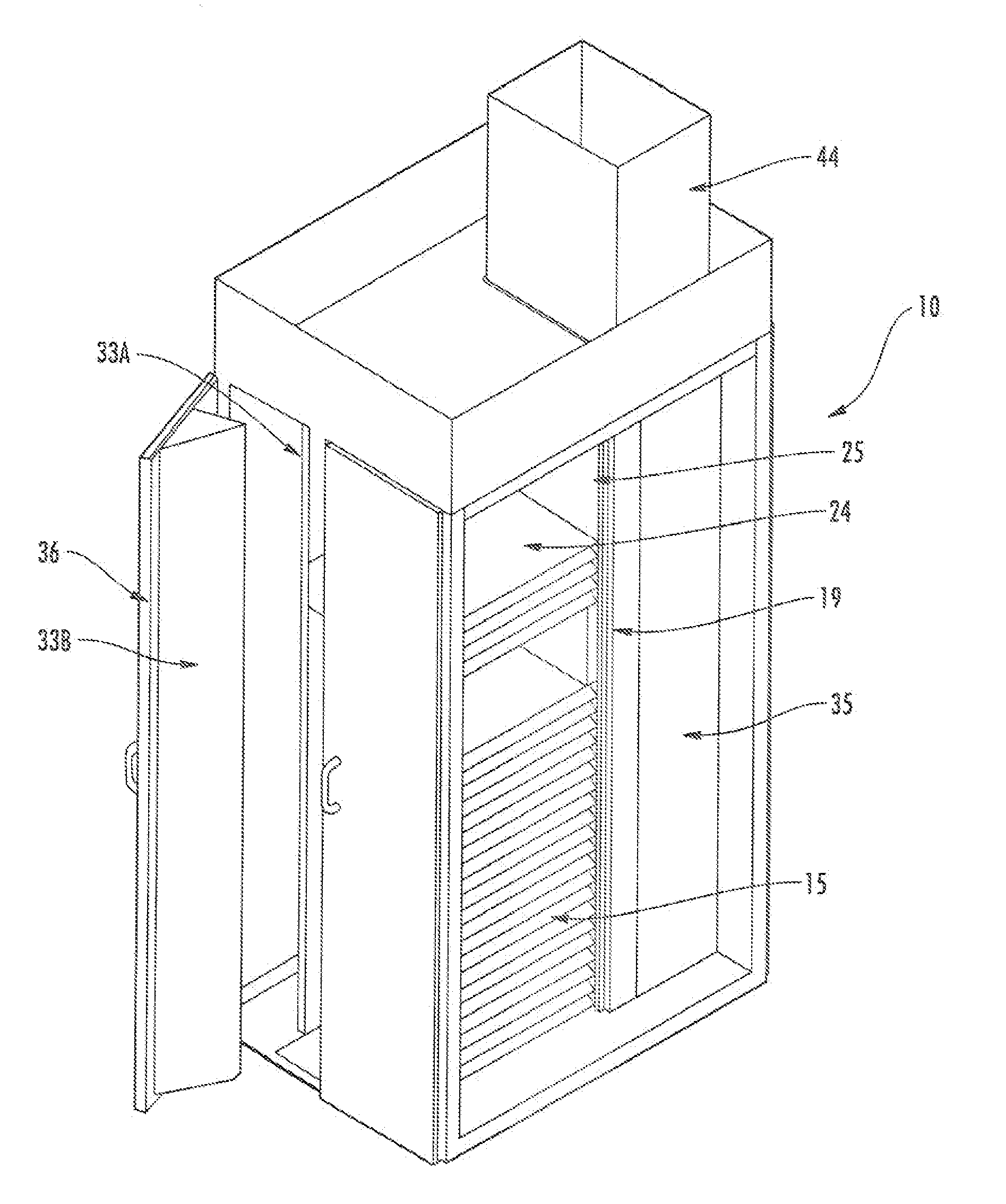
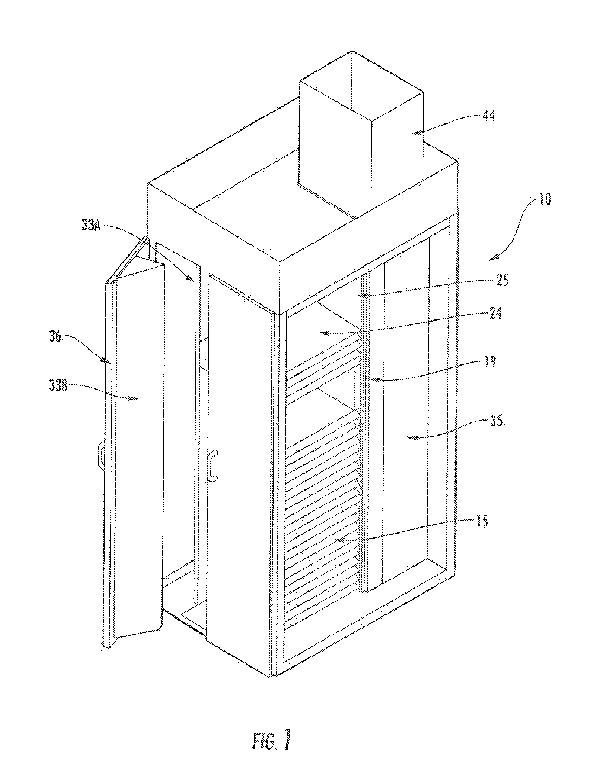
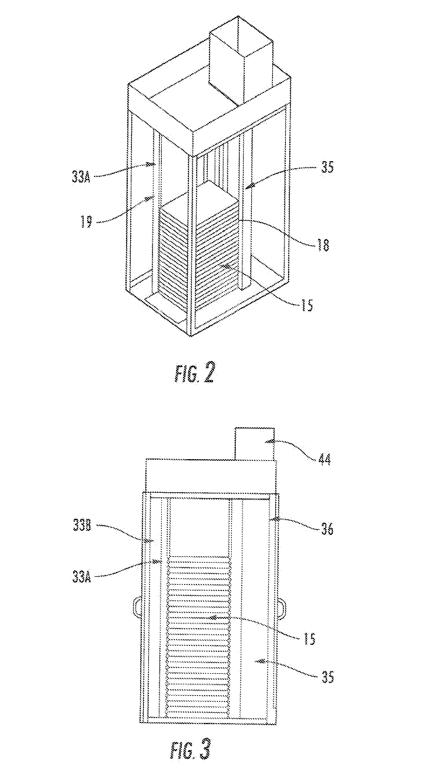
[0030]Referring to the drawings, an exemplary thermal management cabinet is illustrated. The cabinet 10 has generally solid side walls 12, a front 14 and a back 16. The cabinet may be used to house a plurality of servers 15 or other pieces of electronic equipment. Suitable dimensions for the cabinet include a height of 7 feet, a width of 3 feet and a depth of 4 feet, although it will be appreciated that the dimensions can be varied to suit any particular application.

[0031]The cabinet 10 may include generally L-shaped horizontal rails 17 attached to and supported by four vertical rail supports 18 which form part of a frame 19 that is positioned in the interior of the ca...


PUM


Abstract

A thermal management cabinet for electronic equipment such as servers, having an opening in the top and bottom of the cabinet. The cabinet extends between a raised access floor of a building carrying cooled air and a drop ceiling for venting heated air. The bottom opening of the cabinet is alignable with an opening in the access floor such that cool air can pass into the cabinet and can flow through the electronic component storage area to the top opening, which is alignable with an opening in the drop ceiling. The cabinet interior is separated into temperature zones comprising at least a cold zone supplied with air from the access floor and a hot zone for venting through the top opening. At least one baffle creates the temperature zones such that air is directed to flow from the cold zone through the electronic component storage area to the hot zone.

Description

CROSS-REFERENCE TO RELATED APPLICATIONS[0001]This is a continuation of U.S. patent application Ser. No. 12 / 626,114, filed Nov. 25, 2009, which claims the benefit of U.S. Provisional Application No. 61 / 119,980, filed Dec. 4, 2008.FIELD OF THE INVENTION[0002]The present application relates to thermal management cabinets for electronic equipment, and particularly to a cabinet system designed to aid in cooling servers and other computing equipment.BACKGROUND[0003]Data centers typically involve a large number of rack-mounted servers that are housed together in cabinets. Cooling of such server racks and cabinets is a major problem, particularly as processors typically produce large amounts of heat. It has been found that for every 1 watt of power used for Information Technology, 0.5 to 2 watts of power are used for cooling the electronic components, and thus the need for cooling uses a very high percentage of the total IT power consumption. The power dissipation of high-performance CPU pr...

Claims


Application Information

Patent Timeline
Patent Type & Authority Applications(United States)
IPC IPC(8): H05K7/20H05K5/02F28F13/12F28D15/00
CPCF28F9/0265F28F9/028H05K7/20836H05K7/20745H05K7/20554H05K7/1497H05K7/20763
Inventor SLESSMAN, GEORGEGOLDMAN, ALEXMELOTTI, KEVINREO, PETERWILLIAMS, JONATHAN
Owner BASELAYER TECH
Why Eureka
Try Eureka