Hydraulic-Electric Regenerative Energy Storage System

a regenerative energy storage and hydroelectric technology, applied in the direction of gas pressure propulsion mounting, ic engine locomotives, propulsion parts, etc., can solve the problem of limited to an optimal efficient charging rate, achieve cost-effective and/or durable overall energy storage system, and reduce the demand on the electric storage battery pack of the vehicl

Inactive Publication Date: 2010-06-17
ENVIRONMENTAL PROTECTION AGENCY US
View PDF25 Cites 57 Cited by
  • Summary
  • Abstract
  • Description
  • Claims
  • Application Information

AI Technical Summary

Benefits of technology

[0015]A hydraulic energy storage system (comprising a hydraulic pump/motor, a high pressure hydraulic accumulator, a low pressure hydraulic accumulator/reservoir, and interconnecting hydraulic lines) is incorporated into a EV, HEV, or PHEV to provide hydraulic regenerative braking and propulsive assistance for the vehicle. Implementation of a low cost and long-lasting hydraulic energy storage system in the vehicle allows significantly reduced de

Problems solved by technology

Regenerative braking in the vehicle is managed to optimize efficiency in recharging the battery pack, and maximize recoverable energy, by prefere

Method used


Image

  • Hydraulic-Electric Regenerative Energy Storage System
  • Hydraulic-Electric Regenerative Energy Storage System
  • Hydraulic-Electric Regenerative Energy Storage System

Examples


Embodiment Construction

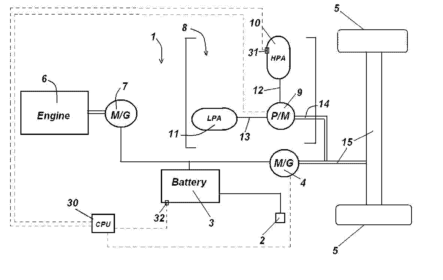
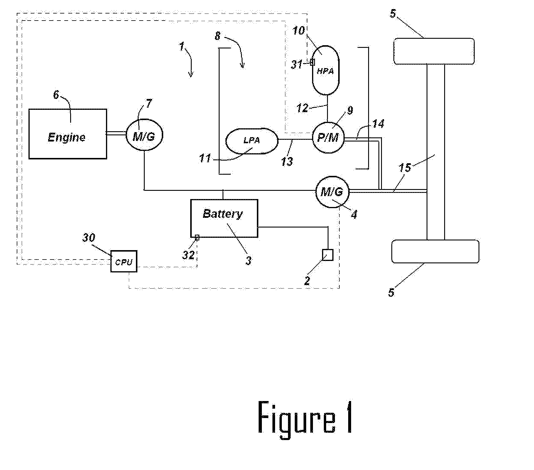
[0024]It will be understood that inverters, switches, reduction gears, and various other components do not need to be shown or discussed for the embodiments discussed here to enable the making and using of the inventions herein, and thus such common features are omitted from the description for purposes of simplicity and better focus on the essential elements of the invention.

[0025]FIG. 1 presents a schematic drawing of a powertrain for one embodiment of a motor vehicle of the present invention. Referring to FIG. 1, plug-in hybrid vehicle 1 includes an electrical outlet 2 for charging of on-board vehicle battery pack 3. As is known in the art, the presence of electrical outlet 2 on the vehicle facilitates charging of the battery pack 3 at homes, offices, or other charging places, thereby allowing the vehicle to be run in large part from energy generated from stationary sources instead of from liquid transportation fuels on board the vehicle. Vehicle 1 may be propelled by battery3 se...


PUM


Abstract

A hydraulic energy storage system (comprising a hydraulic pump/motor, a high pressure hydraulic accumulator, a low pressure hydraulic accumulator/reservoir, and interconnecting hydraulic lines) is incorporated into a EV, HEV, or PHEV to provide hydraulic regenerative braking and propulsive assistance for the vehicle. Implementation of the low cost and long-lasting hydraulic energy storage system in the vehicle, together with the electric energy storage system (comprising a motor/generator and battery pack) of the vehicle, allows significantly reduced demands and higher operating efficiencies for the battery pack, thereby facilitating a more cost-effective, efficient and/or durable overall energy storage system for the vehicle.

Description

CROSS-REFERENCE TO RELATED APPLICATIONS[0001]This application is a continuation-in-part of U.S. patent application Ser. No. 11 / 807,405 “Regenerative Energy Storage System for Hybrid Locomotive,” filed May 29, 2007, and also claims priority from U.S. Provisional Patent Application 61 / 274,138, “Hydraulically Assisted Plug-In Hybrid Electric Vehicle,” filed Aug. 13, 2009.BACKGROUND OF THE INVENTION[0002]1. Field of the Invention[0003]This invention relates to regenerative braking and energy storage systems for motor vehicles.[0004]2. Description of the Related Art[0005]Electric vehicles (EVs), hybrid electric vehicles (HEVs), and plug-in hybrid electric vehicles (PHEVs) provide highly desirable benefits in being able to reduce consumption of liquid transportation fuels. However, industry has not yet found a battery technology that is sufficiently low cost and durable to achieve widespread commercialization and consumer acceptance of these vehicles without large subsidies.[0006]The pred...

Claims


Application Information

Patent Timeline
IPC IPC(8): B60W10/18B60K6/12B60W20/00
CPCB60K6/12Y10T477/24B60K6/543B60T1/10B60W10/08B60W2510/244B61C7/00B61C17/06Y02T10/6208Y02T10/6217Y02T10/6282Y02T30/18Y02T90/14B60W30/18127B60W20/1062B60L1/003B60L11/002B60L2200/26B60K6/46B60W20/14B60L50/90Y02T10/62Y02T30/00B60W20/13
Inventor READ, DAVID H.
Owner ENVIRONMENTAL PROTECTION AGENCY US
Why Eureka
Try Eureka