Methods and systems for efficiently orienting an agile vehicle using a gyroscope array

a technology of gyroscope array and gyroscope array, which is applied in the field of spacecraft attitude control systems, can solve the problems of limiting the amount of useful torque an individual cmg can produce, limiting the ability of the cmg array to produce torque in certain directions, and achieving the gimbal rotation rate or gimbal ra

Inactive Publication Date: 2010-06-17
HONEYWELL INT INC
View PDF31 Cites 22 Cited by
  • Summary
  • Abstract
  • Description
  • Claims
  • Application Information

AI Technical Summary

Benefits of technology

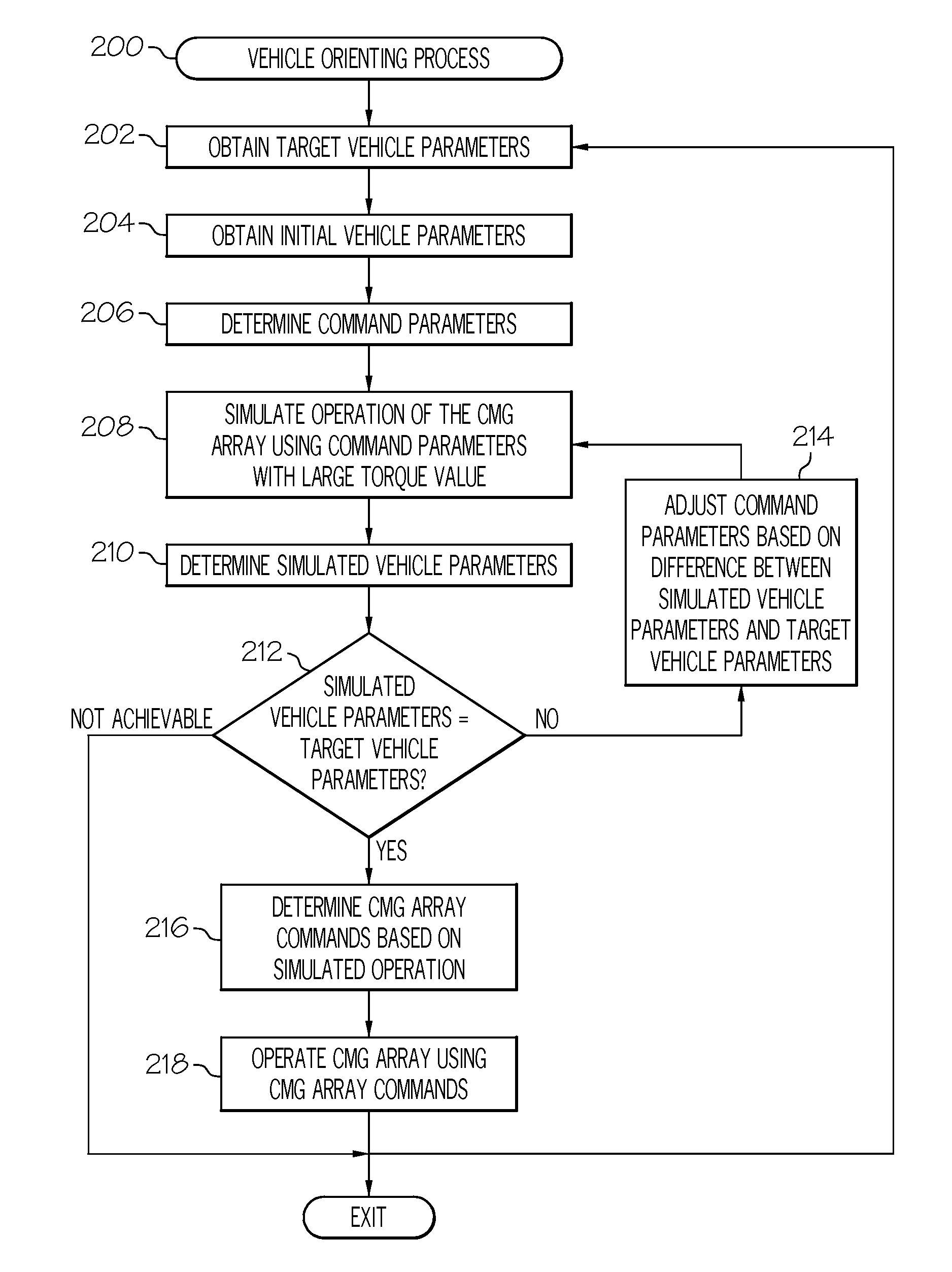
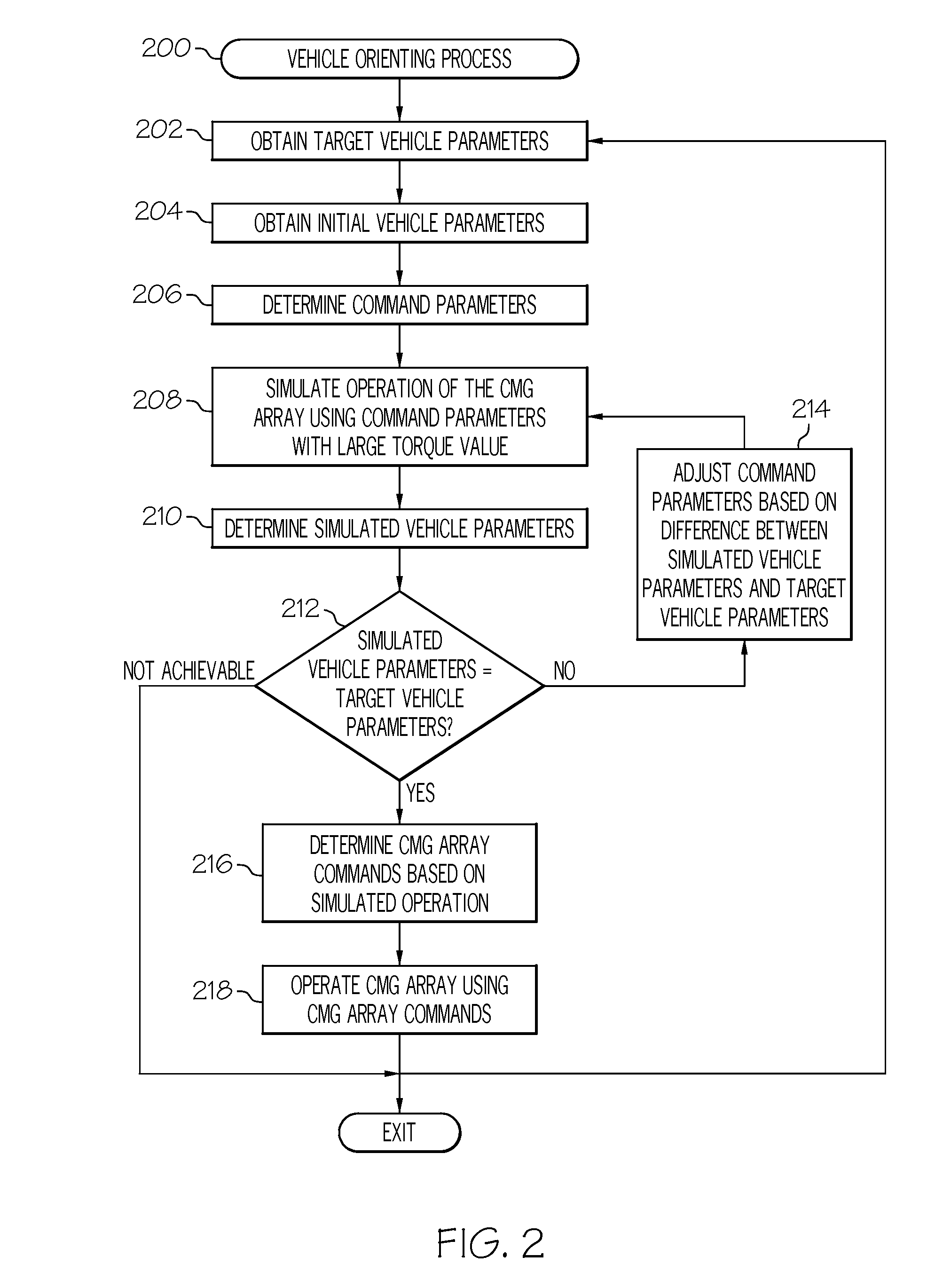
[0005]A method is provided for orienting a vehicle using a control moment gyroscope array. The method comprises obtaining initial vehicle parameters for the vehicle and obtaining target vehicle parameters for the vehicle. The method further comprises determining command parameters based on a difference between the target vehicle parameters and the initial vehicle parameters, and simulating operation of the control moment gyroscope array using the command parameters and a torque value being at least equal to a maximum achievable torque for the control moment gyroscope array. When the simulated vehicle parameters are substantially equal to the target vehicle parameters, the method further comprises determining a torque profile for the control moment gyroscope array based on the simulated operation and operating the control moment gyroscope array using the torque profile.
[0006]In another embodiment, an attitude control system for an agile vehicle is provided. The attitude contro

Problems solved by technology

In addition, the maximum achievable rate of rotation of the gimbal (or gimbal rate) for the individual CMGs is limited by hardware, which in turn limits the amount of useful torque an individual CMG can produce.
Also, particular arra

Method used


Image

  • Methods and systems for efficiently orienting an agile vehicle using a gyroscope array
  • Methods and systems for efficiently orienting an agile vehicle using a gyroscope array
  • Methods and systems for efficiently orienting an agile vehicle using a gyroscope array

Examples


Embodiment Construction

[0010]The following detailed description is merely exemplary in nature and is not intended to limit the subject matter of the application and uses thereof. Furthermore, there is no intention to be bound by any theory presented in the preceding background or the following detailed description.

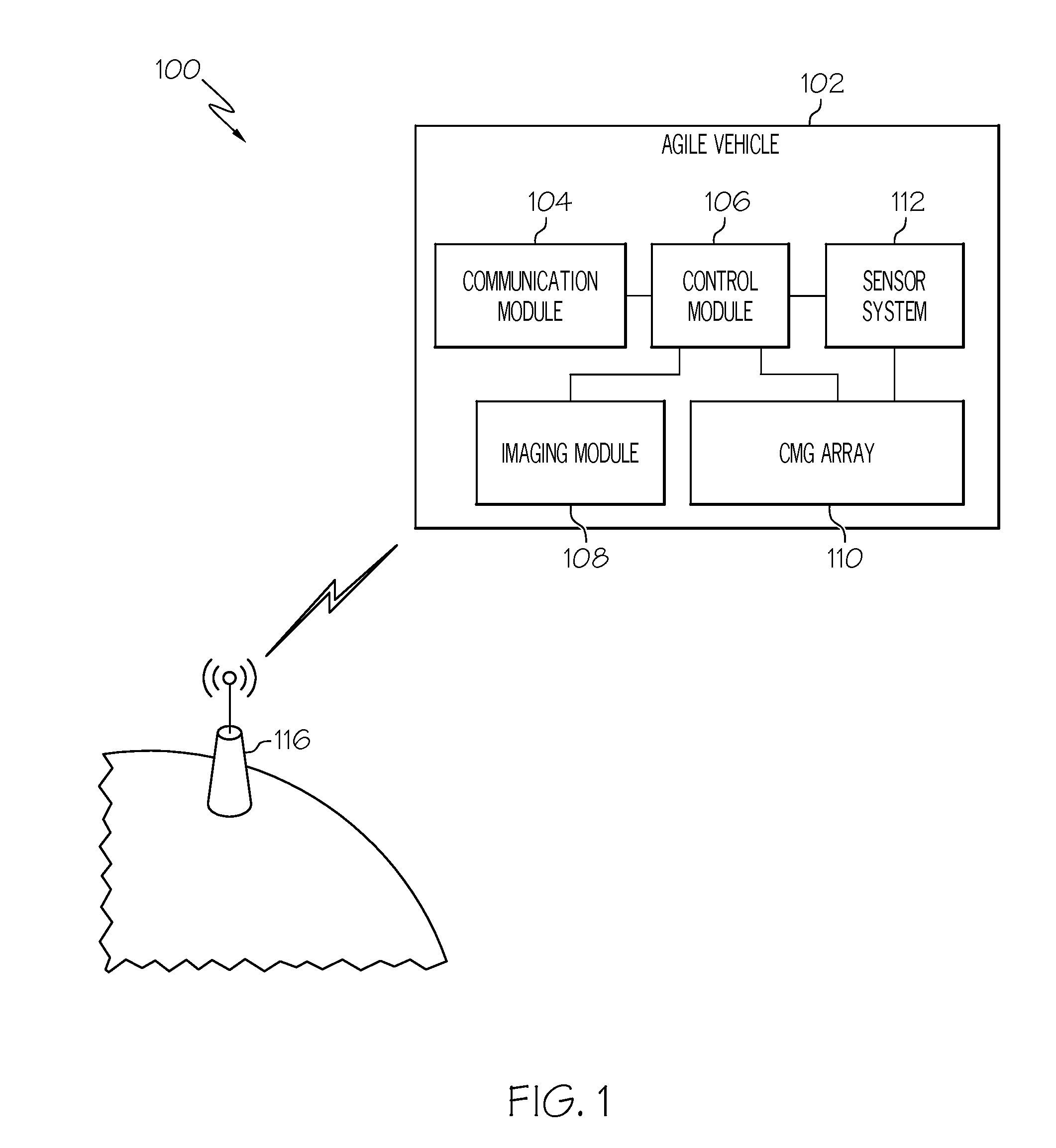
[0011]Techniques and technologies may be described herein in terms of functional and / or logical block components, and with reference to symbolic representations of operations, processing tasks, and functions that may be performed by various computing components or devices. It should be appreciated that the various block components shown in the figures may be realized by any number of hardware, software, and / or firmware components configured to perform the specified functions. For example, an embodiment of a system or a component may employ various integrated circuit components, e.g., memory elements, digital signal processing elements, logic elements, look-up tables, or the like, which may carry...


PUM


Abstract

Methods and systems are provided for orienting an agile vehicle using a control moment gyroscope array. A method comprises obtaining initial vehicle parameters for the vehicle and obtaining target vehicle parameters for the vehicle. The method further comprises determining command parameters based on a difference between the target vehicle parameters and the initial vehicle parameters, and simulating operation of the control moment gyroscope array using the command parameters and a torque value being at least equal to a maximum achievable torque for the control moment gyroscope array. When the simulated vehicle parameters are substantially equal to the target vehicle parameters, the method further comprises determining a torque profile for the control moment gyroscope array based on the simulated operation and operating the control moment gyroscope array using the torque profile.

Description

TECHNICAL FIELD[0001]The subject matter described herein relates generally to spacecraft attitude control systems, and more particularly, embodiments of the subject matter relate to methods and systems for orienting an agile vehicle using a gyroscope array.BACKGROUND[0002]Gyroscopes are currently used in a number of military and civilian applications. One common application involves using gyroscopes, known as control moment gyroscopes (CMGs) to control the attitude or orientation of a spacecraft. A CMG comprises a spinning rotor and one or more motorized gimbals, which are used to rotate the rotor (e.g., gimballing), which in turn alters the angular momentum of the rotor. This change in angular momentum produces a reactionary torque which causes the spacecraft to rotate to the desired attitude or orientation. Attitude control system and other spacecraft orienting applications generally utilize at least three CMGs, also known as a CMG array.[0003]The direction of torque capable of be...

Claims


Application Information

Patent Timeline
IPC IPC(8): G06F19/00
CPCB64G1/286G05D1/0883B64G1/244
Inventor HAMILTON, BRIAN
Owner HONEYWELL INT INC
Why Eureka
Try Eureka