Controlling and dynamically varying automatic parallelization

a technology of automatic parallelization and control, applied in the field of computer systems, can solve the problems of increasing the noise effect of circuit noise on the chip and propagation delay, increasing the power consumption of each new generation of processors, and increasing the difficulty of hardware design performan

Active Publication Date: 2010-06-17
ORACLE INT CORP
View PDF20 Cites 28 Cited by
  • Summary
  • Abstract
  • Description
  • Claims
  • Application Information

AI Technical Summary

Benefits of technology

[0015]In yet another embodiment, a computer readable storage medium is provided that stores program instructions operable to automatically control run-time parallelization of a software application. The program instructions are executable to perform the steps described above regarding a method.

Problems solved by technology

As generating performance from hardware design becomes increasingly difficult, attention turns to new methods of software design.
This reduction leads to increases in cross capacitance effects on wires, parasitic inductance effects on wires, and electrostatic field effects within transistors, which increase the circuit noise effects on-chip and propagation delays.
This trend leads to an increase in power consumption with each new generation of processors.
The operational frequency is limited by these noise and power effects, which may limit the performance of the hardware.
Attention turns to software as programmers may not be able to rely on ever-faster hardware to hide inefficient code and as the need to generate performance from applications executed on multi-core chips increases.
These systems will have lots of hardware threads but are not expected to run at much higher clock frequencies.
This poses a problem on an over-subscribed system when there are more ready-to-run software threads compared to available hardware thread contexts, or if not all threads or groups of threads are equal.
However, such an approach needs one or more queries to the operating system, and often consumes thousands of cycles.

Method used


Image

  • Controlling and dynamically varying automatic parallelization
  • Controlling and dynamically varying automatic parallelization
  • Controlling and dynamically varying automatic parallelization

Examples


Embodiment Construction

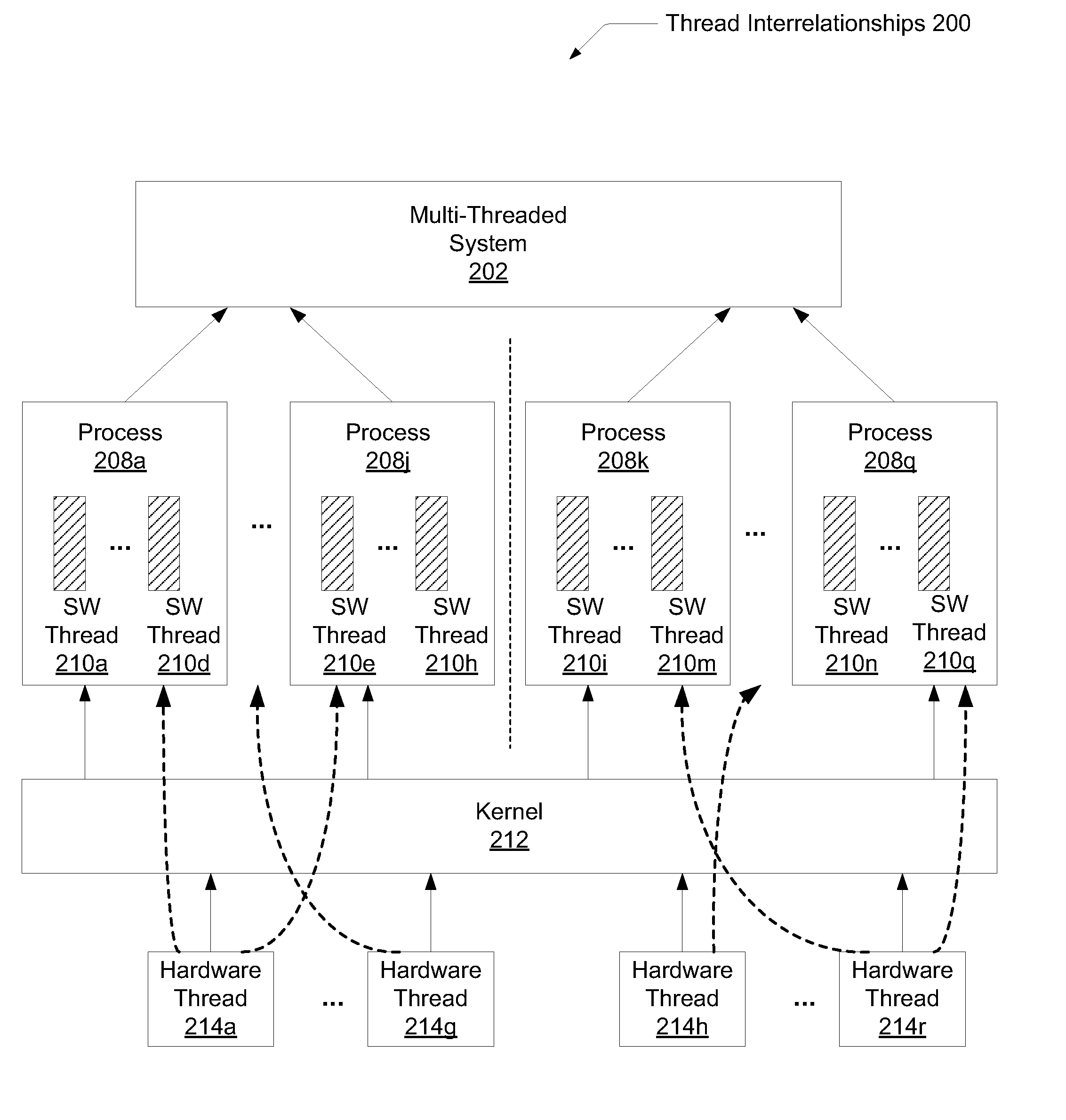
[0021]Referring to FIG. 1, one embodiment of a multi-core microprocessor 100 is shown. Microprocessor 100 may have multiple cores 102a-102d. As used herein, elements referred to by a reference numeral followed by a letter may be collectively referred to by the numeral alone. For example, cores 102a-102d may be collectively referred to as cores 102. Each core 102 may include a superscalar microarchitecture with one or more multi-stage pipelines. Each core 102 may be configured to execute instructions of software applications corresponding to an instruction set architecture (ISA) such as x86, SPARC, PowerPC, MIPS, ARM, or other. Also, each core 102 may be designed to execute multiple strands, or threads. For example, a multi-thread software application may have each of its software threads scheduled to be executed on a separate pipeline within a core 102, or alternatively, a pipeline may process multiple threads via control at certain function units. Each core 102 may comprise a first...


PUM


Abstract

A system and method for automatically controlling run-time parallelization of a software application. A buffer is allocated during execution of program code of an application. When a point in program code near a parallelized region is reached, demand information is stored in the buffer in response to reaching a predetermined first checkpoint. Subsequently, the demand information is read from the buffer in response to reaching a predetermined second checkpoint. Allocation information corresponding to the read demand information is computed and stored the in the buffer for the application to later access. The allocation information is read from the buffer in response to reaching a predetermined third checkpoint, and the parallelized region of code is executed in a manner corresponding to the allocation information.

Description

BACKGROUND OF THE INVENTION[0001]1. Field of the Invention[0002]This invention relates to computer systems, and more particularly, to automatically controlling run-time parallelization of a software application.[0003]2. Description of the Relevant Art[0004]The performance of computer systems is dependent on both hardware and software. As generating performance from hardware design becomes increasingly difficult, attention turns to new methods of software design. For example, regarding the hardware of a system, the geometric dimensions of devices and metal routes on each generation of semiconductor chips continue to decrease. This reduction leads to increases in cross capacitance effects on wires, parasitic inductance effects on wires, and electrostatic field effects within transistors, which increase the circuit noise effects on-chip and propagation delays. In addition, the number of nodes that may switch per clock cycle significantly increases as more devices are used in each new g...

Claims


Application Information

Patent Timeline
Patent Type & Authority Applications(United States)
IPC IPC(8): G06F9/50
CPCG06F9/485
Inventor SONG, YONGHONGKALOGEROPULOS, SPIROSTIRUMALAI, PARTHA P.
Owner ORACLE INT CORP
Why Eureka
Try Eureka