Filter assembly

Active Publication Date: 2010-06-24
PARKER HANNIFIN LTD HEMEL HEMPSTEAD
View PDF24 Cites 21 Cited by
  • Summary
  • Abstract
  • Description
  • Claims
  • Application Information

AI Technical Summary

Benefits of technology

[0031]Preferably, the ejector part is provided toward the second end of the primary chamber. More preferably, the ejector part is provided within the primary chamber. Providing the ejector part in the primary chamber ensures that the ejector part will not interfere with the flow of fluid through the filter assembly once it has passed through the primary chamber.
[0032]The ejector part can be provided as a separate piece to the internal walls of the head part. Preferably, the ejector part is provided by an insert that is separate to the internal walls of the head part. Preferably, at least a portion of the

Problems solved by technology

In particular, filter elements have a limited lifetime and the accumulation of contaminants with prolonged use gives rise to unacceptable pressure drop, which can lead to reentrainment of t

Method used


Image

  • Filter assembly
  • Filter assembly
  • Filter assembly

Examples


Example

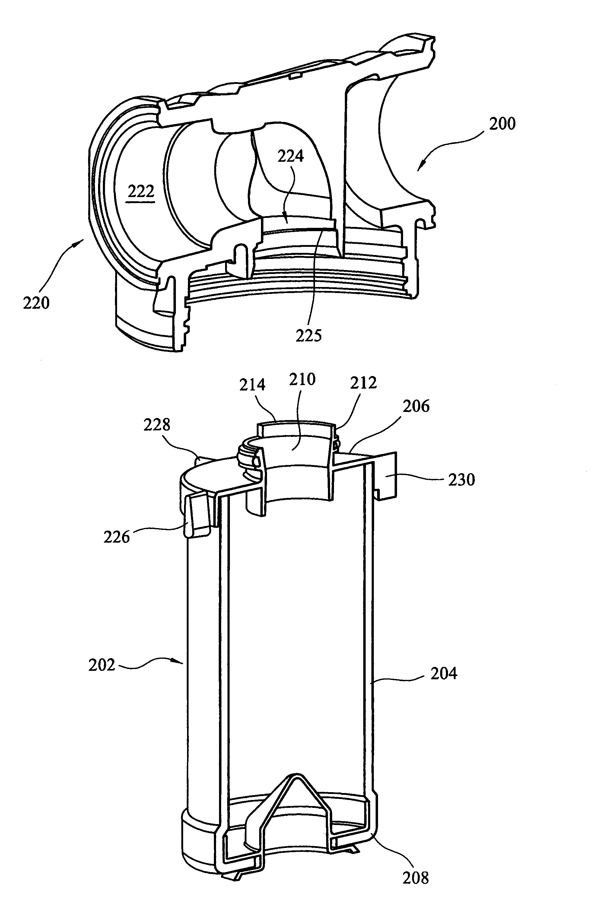
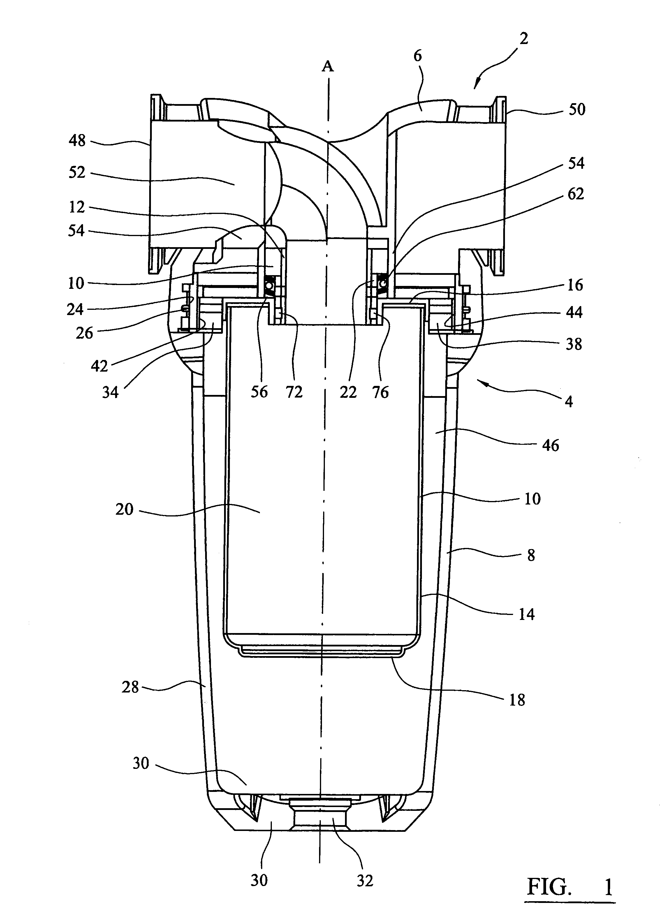
[0055]Referring to the drawings, FIG. 1 shows a filter assembly 2 which comprises a housing 4, having a head part 6 and a body part 8, a filter element 10, and a flow controller 12. The head 6 and body 8 parts each have engagement formations in the form of co-operating screw threads 24, 26 which allow the head 6 and body 8 parts to be connected to one another and separated by relative rotation about axis A. The head part 6 has a head axis and the body part 8 has a body axis, each of which are co-axial with the axis A.

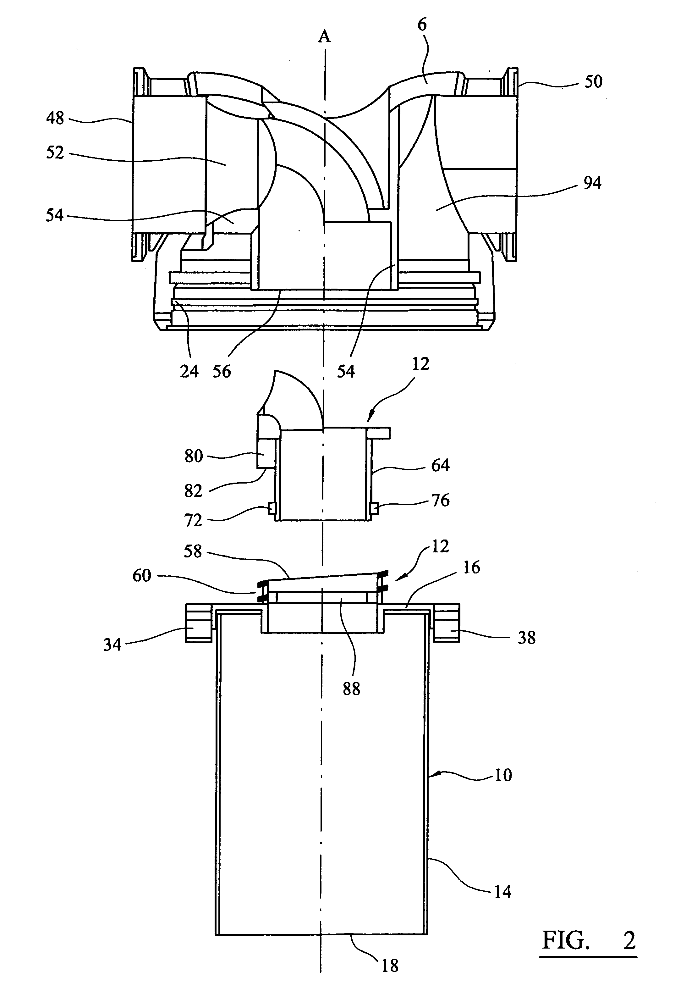
[0056]In the embodiment described, the filter element 10 is a filter element 10 which comprises a cylindrical wall section 14 formed from a filter medium, and top 16 and bottom 18 end caps. As best shown in FIGS. 2 to 4, the wall section 14 of the filter element 10 defines a hollow space 20 within it.

[0057]The top 16 and bottom 18 end caps are formed from a polymeric material. As will be understood, suitable polymeric materials include polyolefins (especially polyethyle...


PUM

PropertyMeasurementUnit
Angleaaaaaaaaaa
Angleaaaaaaaaaa

Abstract

A filter assembly for removing material entrained in a fluid stream includes a housing having a head part and a body part, and inlet and outlet ports for the fluid that is to be filtered, in which at least one of the ports is provided in the head part, the head part having a chamber port fluidly connected to the at least one port in the head part, the head and body parts having first formations which enable them to be connected to one another and separated by relative rotation. The assembly includes a filter element for removing material entrained in the fluid stream that can be received in the body part, the filter element and body part having second formations which restrict relative rotation between them, the filter element having a filter port, in which a fluid tight connection can be provided between the filter port and the chamber port by sliding one of them into the other along a first axis. One of the head part and the filter element provides an inclined surface which is inclined relative to the first axis, and the other provides an ejector part which can act against the said inclined surface so as to push the filter element away from the head part as the head part and the body part are separated by relative rotation, so as to free the filter port from the chamber port.

Description

CROSS REFERENCE TO RELATED APPLICATIONS[0001]This application is a continuation of co-pending International Application No. PCT / GB2008 / 002611 filed Jul. 31, 2008, which application designated the United States, and which application claims priority to Great Britain Application No. 07157247.3, filed Aug. 4, 2007, the disclosure of each of which is incorporated herein by reference.TECHNICAL FIELD[0002]This invention relates to a filter assembly for removing material that is entrained in a fluid stream.BACKGROUND OF THE INVENTION[0003]Filtration of a fluid, such as a gas in a compressed gas system is generally required so that the fluid is sufficiently free of contaminants (liquid, solid or gaseous) for a subsequent application or to minimise adverse effects of contaminants on components of the system. For example, removal of compressor oil from a compressed gas stream can be required to minimise chemical contamination and accumulation on valves which might lead to malfunction of the v...

Claims


Application Information

Patent Timeline
IPC IPC(8): B01D35/30
CPCB01D46/2411B01D2265/025B01D2265/021
Inventor BITTLE, THOMAS S.LANE, BRIAN
Owner PARKER HANNIFIN LTD HEMEL HEMPSTEAD
Why Eureka
Try Eureka