Urea storage system

a storage system and urea technology, applied in the direction of machines/engines, liquid transfer devices, positive displacement liquid engines, etc., can solve the problems of not having pumps and not being able to provide urea to the exhaust treatment system, and achieve the effect of quick freezing of frozen urea

Inactive Publication Date: 2010-06-24
DELPHI TECH INC
View PDF8 Cites 32 Cited by
  • Summary
  • Abstract
  • Description
  • Claims
  • Application Information

AI Technical Summary

Benefits of technology

[0007]The present invention provides a simple mechanism for pumping urea solution in applications where urea is subject to freeze / thaw cycles. Such applications include motor vehicles that are subject to ambient temperatures below the freezing point of the urea solution. The simplicity of the disclosed pumping mechanism is tolerant of frozen urea solution and provides a method of quickly thawing frozen urea for maintaining liquid urea for exhaust treatment. The present invention resumes pumping when the urea solution within it has been sufficiently heated to return to a liquid state.

Problems solved by technology

Present designs do not have pumps due to cost and reliability issues related to freezing and thawing of the urea solution.
However, if the solution level in the storage tank is low, such as 25% full, the solution level in the reservoir is not sufficient to supply the amount of urea demanded until the outer tank thaws, which may not be sufficient to provide urea to the exhaust treatment system.

Method used


Image

  • Urea storage system
  • Urea storage system
  • Urea storage system

Examples


Embodiment Construction

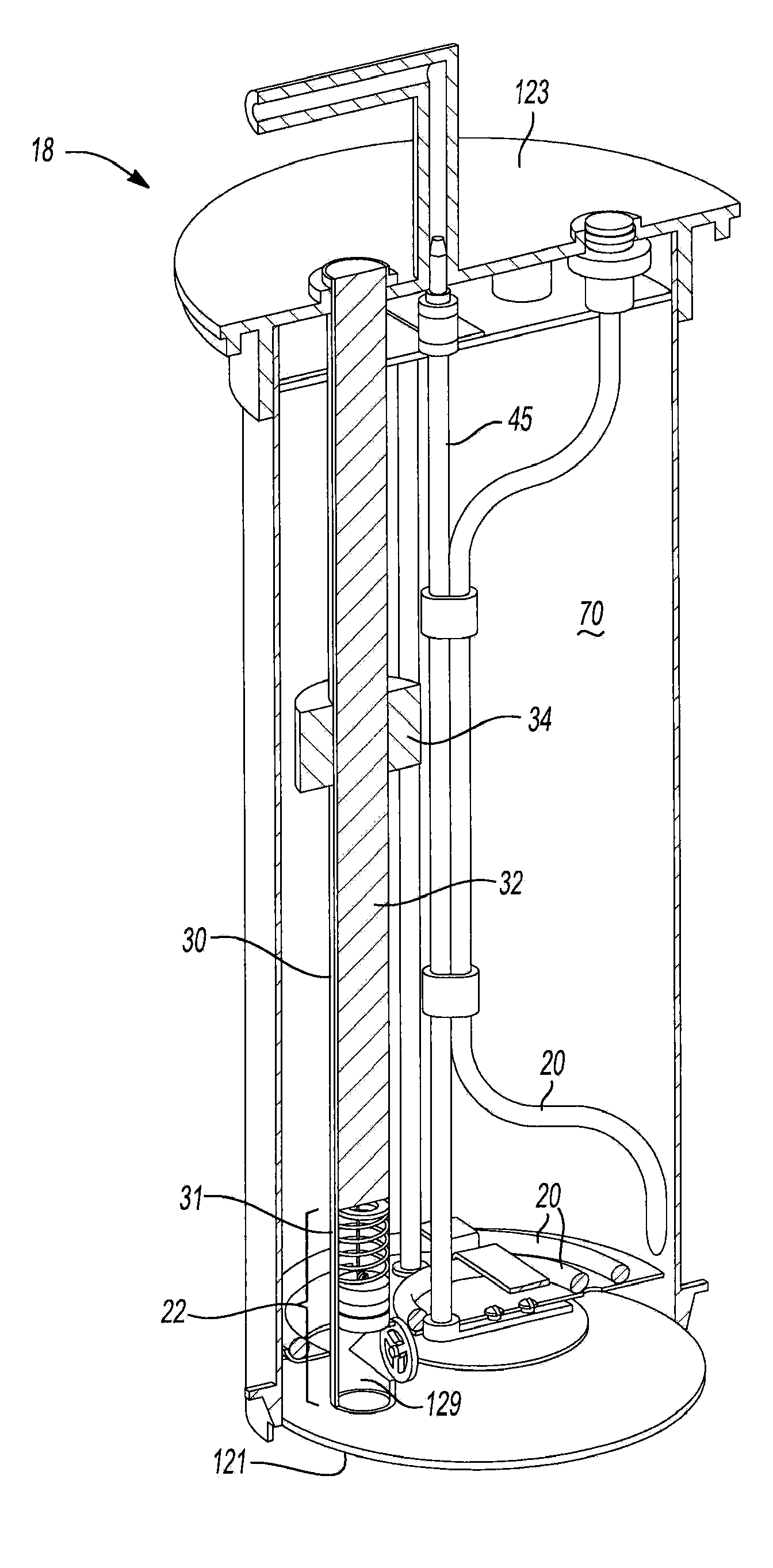
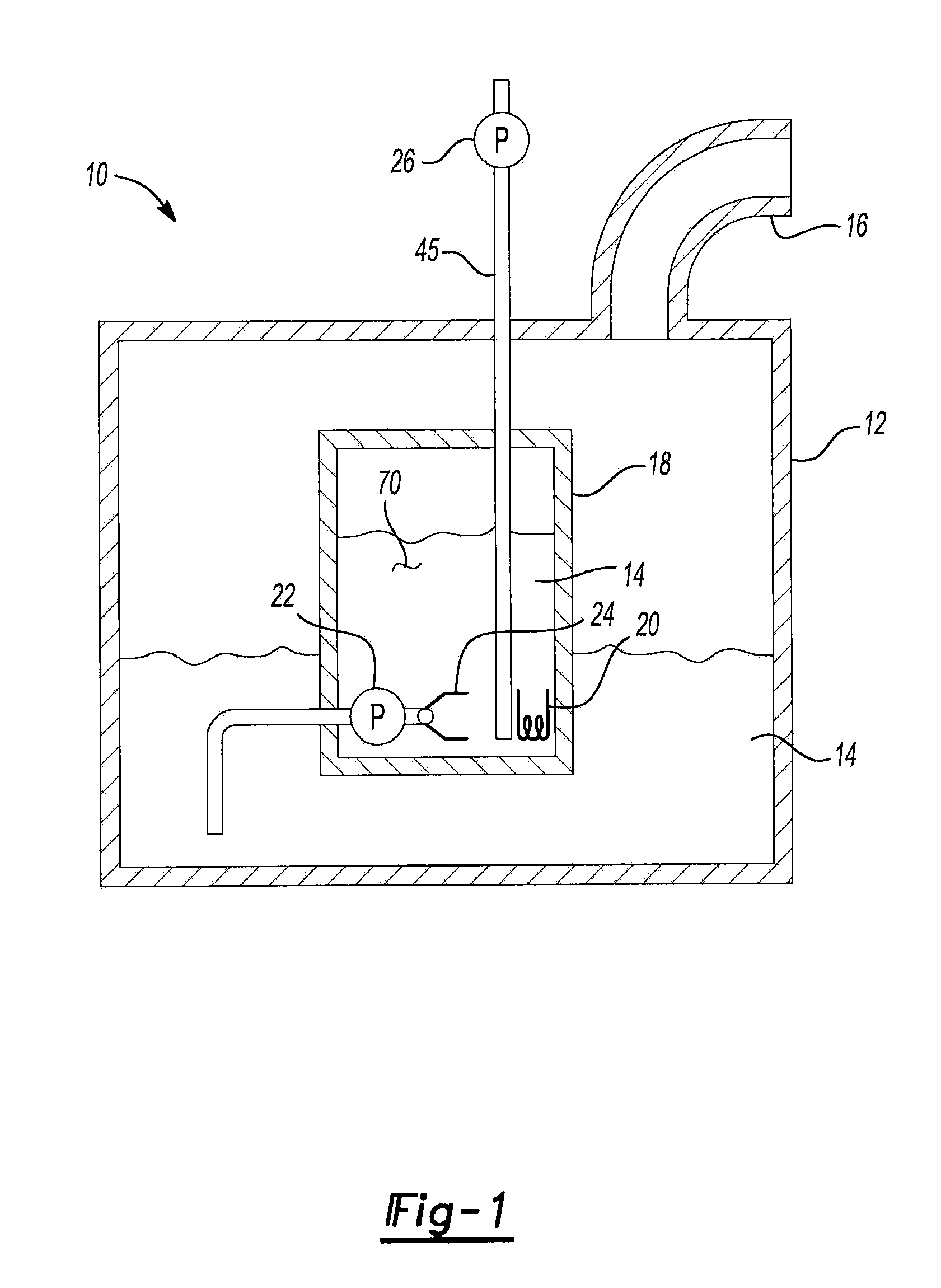
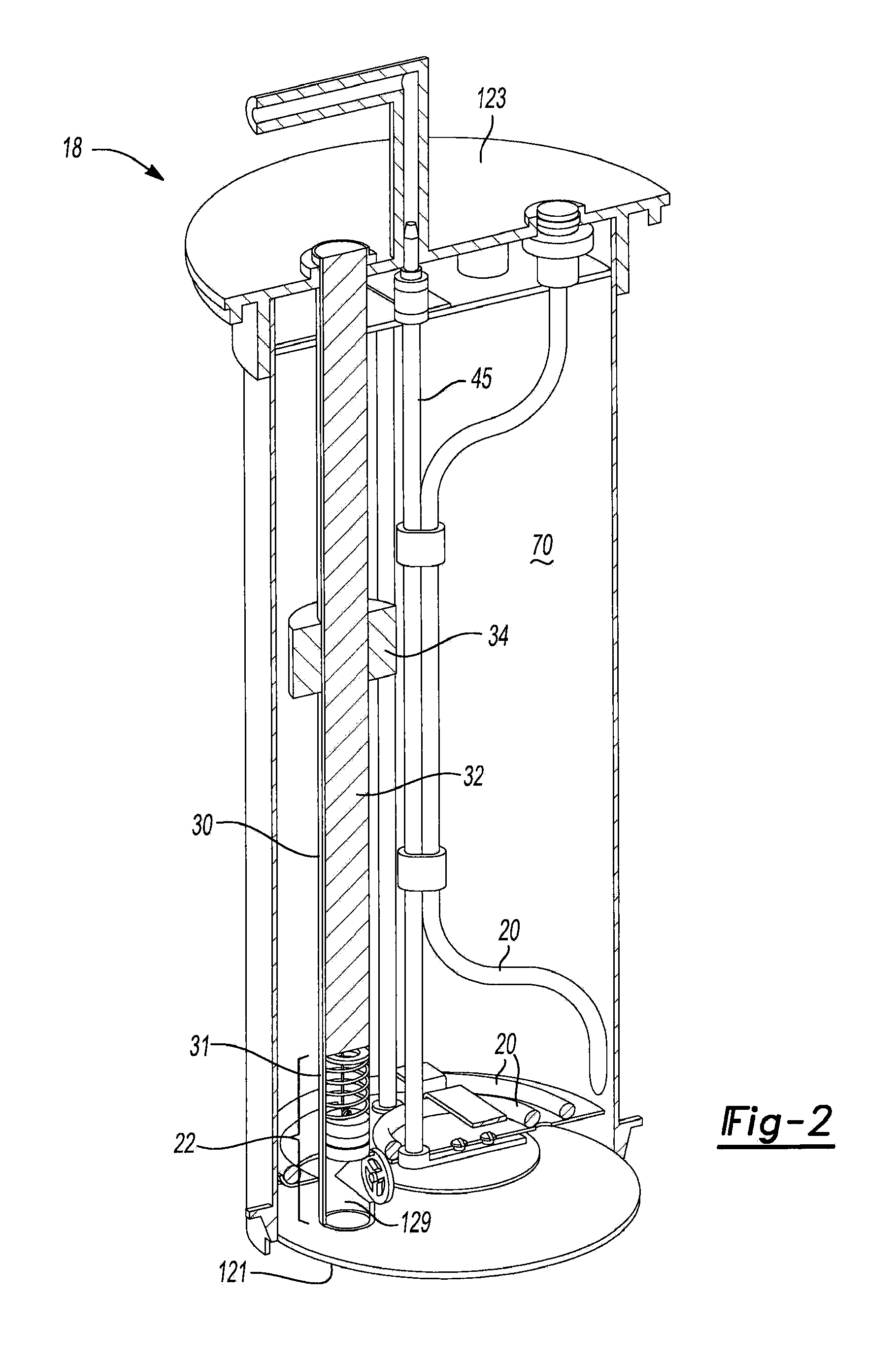
[0013]Referring now to FIG. 1, a functional block diagram is shown of a urea storage system 10. Storage system 10 includes a storage tank 12 that contains a urea solution 14. Urea solution 14 can be refilled via a filler opening 16. Storage tank 12 includes a reservoir 18. Reservoir 18 contains a portion of solution 14 within a volume that can be heated by a heater 20. A pump 22 pumps solution 14 into reservoir 18. The level of solution 14 can therefore be higher than the solution level in tank 12 providing a pressure load in reservoir 18 that is greater than the pressure head within tank 12. A check valve 24 prevents solution 14 from draining out of reservoir 18 and returning to storage tank 12. Another pump 26 transports solution 14 from reservoir 18 to a urea injection system that injects solution 14 into the engine exhaust stream.

[0014]Referring now to FIG. 2, one of several embodiments is shown of reservoir 18. Reservoir 18 includes a level sensing tube 30 that contains a print...


PUM


Abstract

A urea storage system comprising a storage tank for a urea solution is provided. The system comprises a heated reservoir, a channel connecting the storage tank to the heated reservoir and a pump for drawing urea from the heated reservoir. A second pump including an actuator comprising a memory shape metal for drawing urea from the storage tank to the heated reservoir is also provided.

Description

[0001]The present disclosure relates to pumps for vehicle mounted urea reservoirs.BACKGROUND OF THE INVENTION[0002]Urea selective catalyst reaction (SCR) systems treat diesel exhaust to reduce tailpipe emissions. A urea and water solution is injected into the exhaust stream. Hydrolysis converts the solution to ammonia upstream of a SCR catalyst converter. The ammonia reacts with NO2 trapped on the SCR catalyst to form N2 and CO2 and thus reduce pollution of the diesel exhaust.[0003]At temperatures below −11° C., the urea solution freezes into solid ice. A thermal heating system thaws the solid ice into liquid solution. A pump transports the thawed solution to an injector that is in the exhaust stream. In order to provide adequate operation during cold weather, a predetermined amount of the urea solution must be proximate the heater and the pump's pickup tube. This is accomplished by using a reservoir within the urea solution storage tank. The reservoir holds the heater and the prede...

Claims


Application Information

Patent Timeline
Patent Type & Authority Applications(United States)
IPC IPC(8): F04B23/04F01N3/00
CPCF01N3/2066F01N2610/02F01N2610/10F01N2610/1406Y02T10/24F04B17/00F04B23/021F05C2251/08F01N2610/1433Y02T10/12Y10T137/86131
Inventor LECEA, OSCAR A.GOULETTE, DAVID A.MCCLANAHAN, MARK R.
Owner DELPHI TECH INC
Why Eureka
Try Eureka