Dispensing device for viscous materials

a dispenser and viscous material technology, applied in the direction of liquid transfer devices, single-unit apparatuses, instruments, etc., can solve the problems of user's hand coming into contact with the product, uncontrollable release, undesired consequences, etc., and achieve the effect of simple production

Active Publication Date: 2010-06-24
THE PROCTER & GAMBLE COMPANY
View PDF12 Cites 24 Cited by
  • Summary
  • Abstract
  • Description
  • Claims
  • Application Information

AI Technical Summary

Benefits of technology

[0009]The present invention addresses these problems by providing a dispenser for viscous materials comprising a housing having a generally elongate axis with a distal end, a proximal end and an interior volume. A moveable wall divides the interior volume of the housing into a distal product chamber and a proximal pressure chamber in pressure communicating relation with one another. An outlet from the product chamber is located adjacent to the distal end of the housing and an air inlet is provided to allow air to enter the pressure chamber. Displacement of the product occurs when accumulated excess air pressure in the pressure chamber acts on the back of the movable wall. The excess air pressure is built up by a bellows arranged in fluid communication with the pressure chamber. On actuation, the bellows can be reduced in volume and subsequently recover by entry of air through the inlet. The direction of force application is preferably perpendicular to the housing axis i.e. having a significant component in the perpendicular direction. According to this preferred arrangement of the invention, a simple lateral squeezing action allows dispensing of a repeatable quantity of product through the outlet. The dispenser may be conveniently held in a user's hand and the bellows assembly may be located for actuation by a user's thumb, fingers or palm.
[0011]In the present context, the term “bellows” is intended to encompass any suitable actuator or recoverable collapsible element or assembly of elements, that can expand and contract in volume by a substantially defined stroke e.g. between a defined starting position and a defined end position. This is thus to be distinguished from squeezable containers where e.g. the product chamber itself is squeezed by a greater or lesser degree to expel a variable quantity of product. The geometry and material composition of the bellows element should be such to allow a compression of bellows volume of preferably 50% or higher, most preferably of 70% or higher, between the expanded and compressed configuration: this ensures an efficient transfer of the actuation pressure applied to the bellows into pressure increase in the pressure chamber. Those skilled in the art understand that this is most easily achieved if the bellows collapse in the compression direction with minimal deformation in other directions. The present invention has been found to give reproducible, substantially constant dosing during the complete dispensing of the product.
[0019]In a preferred embodiment of the invention, the housing comprises a cylinder and the moveable wall comprises a piston, axially slideable within the cylinder. Such piston-cylinder arrangements can be extremely effective in providing full evacuation of the product chamber. To achieve this, the piston should preferably have a flexible sealing edge and the cylinder should be generally smooth. In the present context it is understood that the cylinder need not be round in cross-section and any form of piston-cylinder arrangement could be employed including generally oval, rectangular, square, elliptical and triangular forms. The piston should preferably slide with relatively low frictional resistance in order to avoid pressure build up in the pressure chamber which would not be transferred to dispensed product. The skilled person will be aware of suitable materials for the piston and cylinder including plastics materials, metals, alloys, composites and glasses. To minimize the coefficient of friction, the cylinder or piston may also be coated e.g. with Teflon or similar coatings. Additionally or alternatively, in order to achieve a low coefficient of friction, the piston and the cylinder would be formed of different materials. Most preferably the cylinder is formed in polypropylene and the piston in polyethylene or a more resilient material. This arrangement allows the piston to re-shape once inserted into the cylinder and match the inner cylinder contour irregularities, thus allowing a better sealing.
[0024]As a result of the arrangement as presently proposed the device may comprises less than eight components, preferably less than six components and more preferably, less than five components. This refers to the in use condition, thus excluding a cap or other packaging. At its very simplest, the dispenser may comprise just three components, namely the housing including an unvalved outlet, the moveable wall and the bellows including an inlet valve. Such an arrangement is extremely simple to produce and may thus be relatively inexpensive.The dispenser may be provided in various forms comprising different utility attachments for different purposes. The utility attachment may be a hair care attachment, a dental care attachment, a paste dispenser, a glue applicator, a mastic applicator, a stain removal tip, a skin care attachment, a dish washing attachment, a toilet brush, a viscous food applicator, a foaming or spraying head, a multiple nozzle head and a shaver head or any other attachment that may be required in combination with the dispensing of a fluid. The attachment may be integrally formed with the housing or attached e.g. releasably thereto. In this manner a single underlying design may be provided for use with different product contents according to the required use. Products that may be contained in the dispenser include hair care products, dental care products, adhesive products, mastic type DIY products, stain removing agents, skin care products, washing products including soaps and detergents, food products, toilet cleaning and other household products.

Problems solved by technology

The release button is frequently located adjacent to the outlet and can lead to the user's hand coming into contact with the product.
In certain cases, the fact that the product is permanently pressurized can lead to undesired consequences.
These may include uncontrolled release due to failure of the valve, accidental actuation and oozing of the product from the outlet after actuation.
These packages are affected by several problems: one is the backward flow of the remaining content of the tube, another is that it is difficult to expel entirely the content of the tube.
U.S. Pat. No. 4,437,591 and U.S. Pat. No. 4,865,231 describe such devices but are relatively complex in their need for numerous mechanical components which are disposed of after use.
Nevertheless, they offer little control over oozing at the outlet and are relatively expensive items to manufacture.
They also require an elongate rod equal in length to the cartridge, which on initial use is inconvenient.
Like aerosols, these devices require the user's finger to be located close to the discharge outlet which in certain situations may be undesirable.
Many of these devices are also unable to operate in an inverted orientation, due to the requirement of a fill-tube extending to the bottom of the reservoir.
This requires the user's hands to be located in the region of the dispenser outlet which may lead to inconvenience.
The construction is also relatively complex, requiring at least six separate components to be assembled.
The squeezing action applied to the container may be convenient for many dispensing situations but does not allow for convenient and accurate dosing of the dispensed quantity.

Method used


Image

  • Dispensing device for viscous materials
  • Dispensing device for viscous materials
  • Dispensing device for viscous materials

Examples


first embodiment

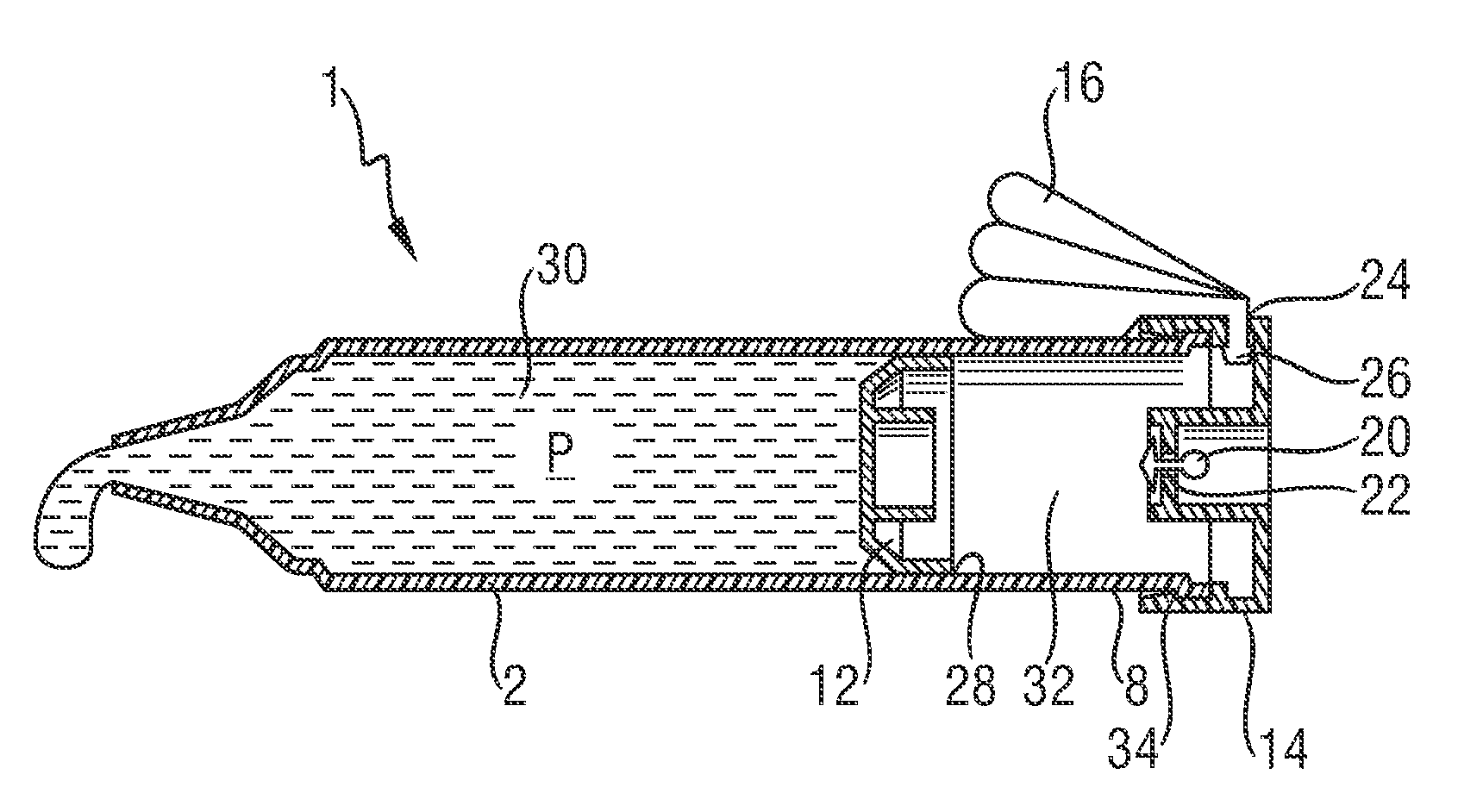
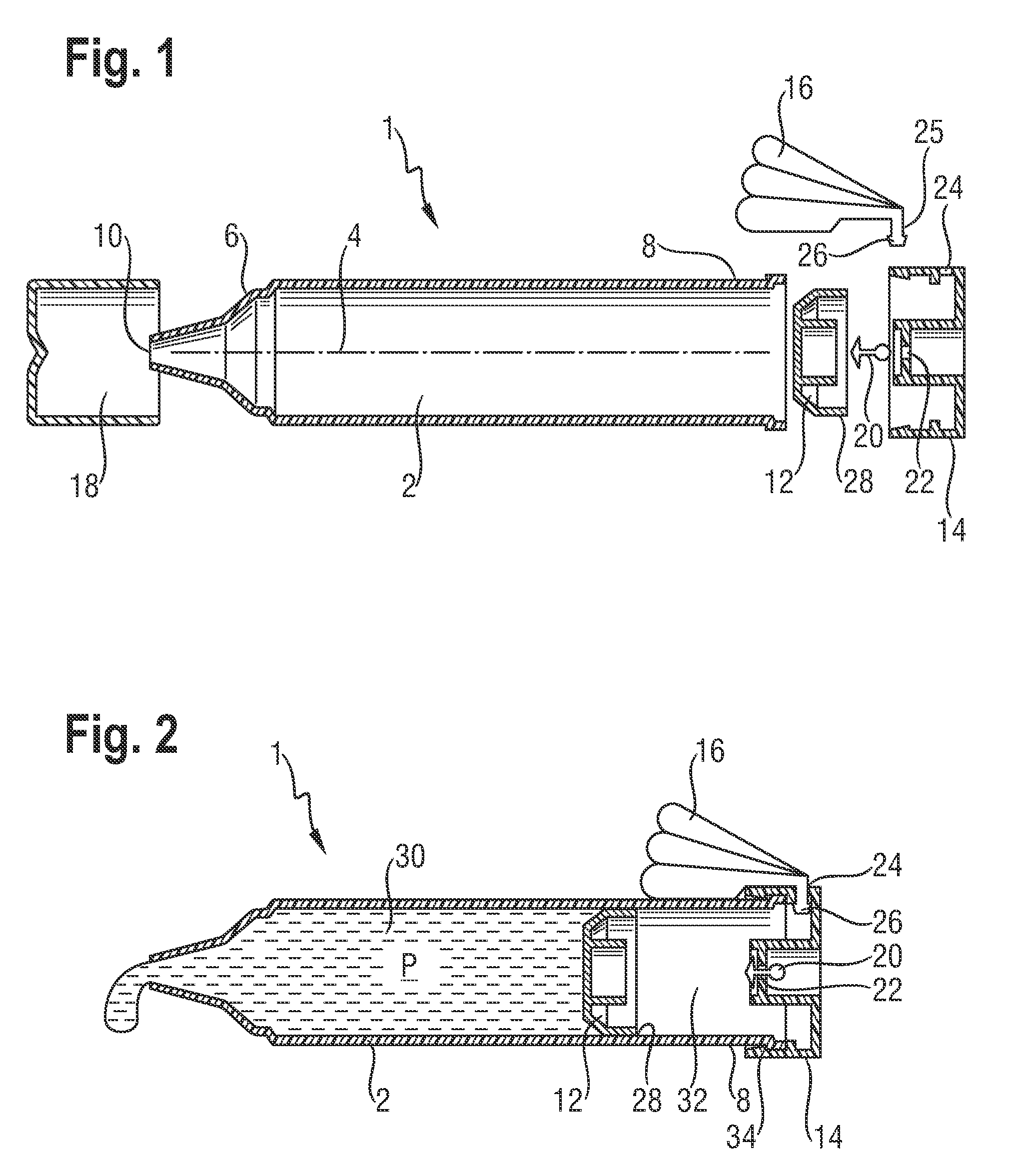
[0037]The following is a description of certain embodiments of the invention, given by way of example only and with reference to the drawings. Referring to FIG. 1, there is shown a dispenser 1 according to the invention in exploded view. The dispenser 1 comprises a tubular housing 2, a piston 12, a bottom cap 14, a bellows 16, a cover 18 and a one-way valve element 20. The housing 2 has a generally elongate axis 4 with a distal end 6 and a proximal end 8. An outlet 10 from an interior of the housing 2 is located at the distal end 6. Bottom cap 14 is generally cup shaped and has a centrally located inlet channel 22 and an opening 24 in its lateral wall. Bellows 16 is formed by blow-molding and has an outlet duct 25 terminating in a nipple 26. Piston 12 has a peripheral seal 28.

[0038]FIG. 2 shows the dispenser 1 of FIG. 1 in longitudinal section in its assembled condition with cover 18 removed. The piston 12 is located within the housing 2 with the peripheral seal 28 forming a sliding...

second embodiment

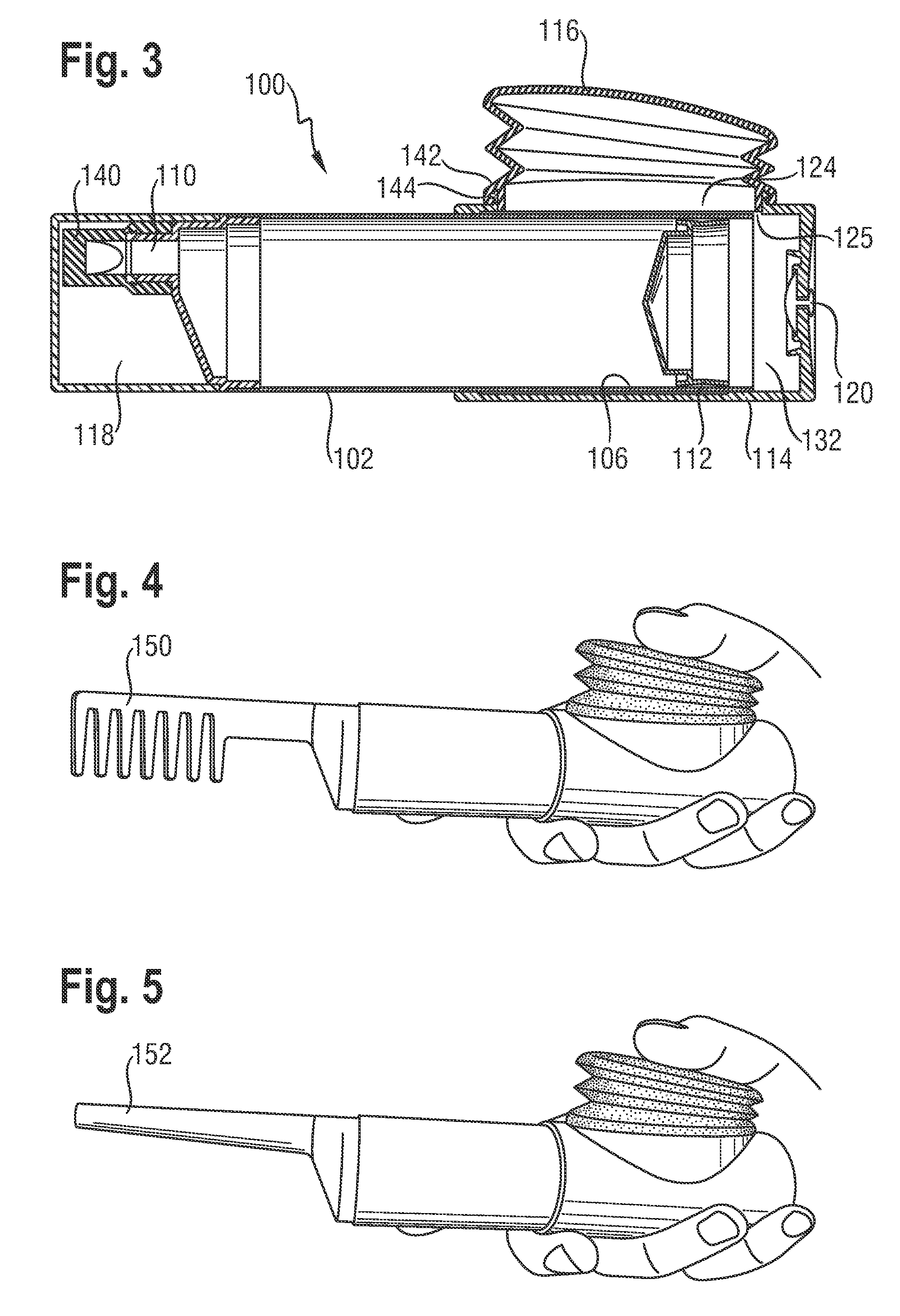
[0041]A dispenser 100 according to the invention is shown in longitudinal cross-section in FIG. 3. Like elements to those of FIG. 1 are designated by the same numeral preceded by 100. According to FIG. 3, the dispenser 100 comprises a housing 102 in which slides piston 112. A bottom cap 114, bellows 116, cover 118 and a one-way valve element 120 are also provided. The dispenser 100 differs from the embodiment of FIG. 1 in that the bottom cap 114 is in the form of a sleeve that generally envelops the distal end 106 of the housing 102. Bottom cap 114 and housing 102 are connected by a bayonet connection (not shown). A further difference is the provision of an outlet check valve 140 extending from the outlet 110. The outlet check valve 140 is in the form of a soft duck-bill valve having a cracking pressure of 1 mbar. One example of such duck-bill valves is commercialized by Verna® Laboratories Inc. in fluorosilicon with the name VA3512. It is noted that the soft tip of the outlet check...


PUM


Abstract

A dispenser for viscous materials has a housing with a moveable wall that divides the interior volume of the housing into a distal product chamber and a proximal pressure chamber. An outlet from the product chamber is located adjacent to the distal end of the housing and an air inlet is provided to allow air to enter the pressure chamber. Displacement of the product occurs when accumulated excess air pressure in the pressure chamber acts on the back of the movable wall. The excess air pressure is built up by a bellows assembly arranged in fluid communication with the pressure chamber. On actuation, the bellows can be reduced in volume and subsequently recover by entry of air through the inlet. The direction of force application is preferably perpendicular to the housing axis and the location of the bellows is preferably distant from the product outlet.

Description

FIELD OF THE INVENTION[0001]The invention relates generally to dispensers for viscous materials and more particularly to hand operated dispensers for viscous fluids, pastes, creams and gels. Such dispensers are particularly useful in the delivery of household, fabric care, hair-care, beauty care, oral-care, do-it-yourself (DIY) and food products.DESCRIPTION OF THE RELATED ART[0002]A wide variety of dispensers are presently known and used. These may conveniently be divided into pressurized and unpressurised systems. Pressurized systems include aerosols and systems based on elastically biased reservoirs. These systems generally require a release button and valve to permit delivery of the pressurized product through a fluid outlet. The release button is frequently located adjacent to the outlet and can lead to the user's hand coming into contact with the product. In certain cases, the fact that the product is permanently pressurized can lead to undesired consequences. These may include...

Claims


Application Information

Patent Timeline
Patent Type & Authority Applications(United States)
IPC IPC(8): B67D7/06
CPCB05C17/00503B05C17/00553B05C17/00583B05C17/015B05B11/0078B65D83/0055B05B11/00B05B11/0045B05B11/0048B65D83/0033B05B11/06B05B11/027B05B11/028
Inventor BARTOLUCCI, STEFANOHOEFTE, PAULUSLAMB, JOHN DAVIDSCOTT, PAUL ROBERTVANDECAPPELLE, PEDRO VINCENT
Owner THE PROCTER & GAMBLE COMPANY
Why Eureka
Try Eureka