
Bale breaker apparatus and method

a bale breaker and bale breaker technology, applied in the field of bale breaker apparatus and method, can solve the problems of weaker livestock becoming undernourished, affecting the quality of bale breaker, and rarely using bale breaker products in baled form

Inactive Publication Date: 2010-06-24
ROTOCHOPPER
View PDF9 Cites 21 Cited by
  • Summary
  • Abstract
  • Description
  • Claims
  • Application Information

AI Technical Summary

Benefits of technology

"The patent describes an auxiliary powerfeed attachable to a fragmentation machine, which includes a pivotable arm and a rotatable drum with angled teeth. The drum can rotate in both directions, and the angled teeth are designed to cut and push the material being processed. The patent also describes a subsystem of the fragmentation machine that includes a conveyor for feeding round bales, a rotatable drum with angled teeth, and a hydraulic motor for rotating the drum. The method for controlling the auxiliary powerfeed involves running the conveyor, detecting the pressure of the hydraulic motor, and rotating the drum in either the forward or reverse direction to cut or push the material on the conveyor. The technical effects of this patent include improved efficiency and control over the processing of material, as well as the ability to handle a variety of materials and production rates."

Problems solved by technology

Yet such products are rarely utilized in baled form.
When bales are set in a cattle pasture, for instance, much of the material ends up trampled into the ground as cows fight for access to the bales.
More dominant livestock often eat more while weaker livestock may become undernourished.
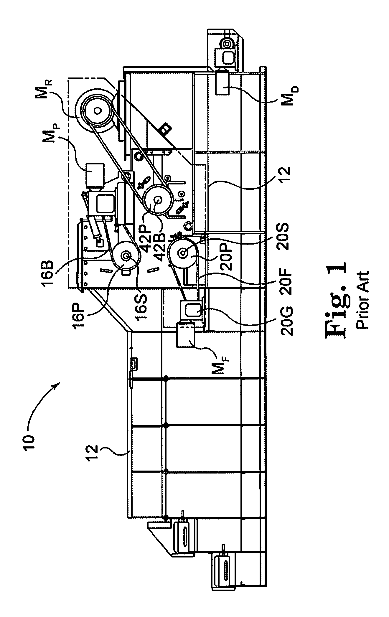
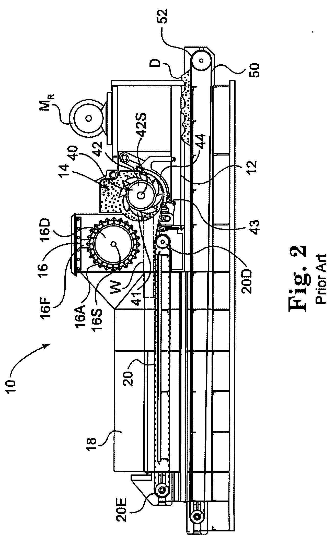
Grinding machines known commercially as horizontal grinders often have feed openings that are too small to effectively or efficiently process round bales.
Yet a standard powerfeed often cannot effectively separate portions from the whole of a bale, crate, or other feedstock described above and still provide the downward pressure necessary to stabilize the separated material.
Round bales are typically tightly compacted and too large to be fed efficiently into a horizontal grinder or, in some cases, to be fed at all.
Yet, even if a tub grinder has a bale breaker device, it still has several limitations that become evident when compared to a horizontal grinder.
Light, loose material has a tendency to float above the rotor, while dense, heavy material may press down upon the rotor, decreasing efficiency.
In some cases, the rotor in a tub grinder may pull material into the grinding chamber too quickly, creating excessive rotor drag, or in more extreme cases, stalling the rotor.
Even if a tub grinder has a preprocessing device, its efficiency and efficacy may also be affected by the weight of the feed material.
Even when the tub stops altogether, however, gravity is still forcing the bale down into the rotor.
If the powerfeed drum is capable of lifting high enough to feed a round bale (or other feedstock mentioned previously), however, a large portion of the rotor is then exposed to the oncoming bale, allowing the rotor to draw too much raw material into the grinding chamber, resulting in decreased efficiency or perhaps plugging.
If the powerfeed drum is incapable of lifting high enough to gain traction on a round bale, it will not be able to feed the bale to the rotor.
In most cases, the cleats or serrated teeth on a powerfeed are incapable to tearing material away from the bale at a controlled rate because the bale may roll backward.
Also, if the cleats / teeth on a powerfeed were long enough to tear material from a bale, they would be ineffective for feedstocks like logs, pallets, and slabs.

Method used


Image

  • Bale breaker apparatus and method
  • Bale breaker apparatus and method
  • Bale breaker apparatus and method

Examples


Embodiment Construction

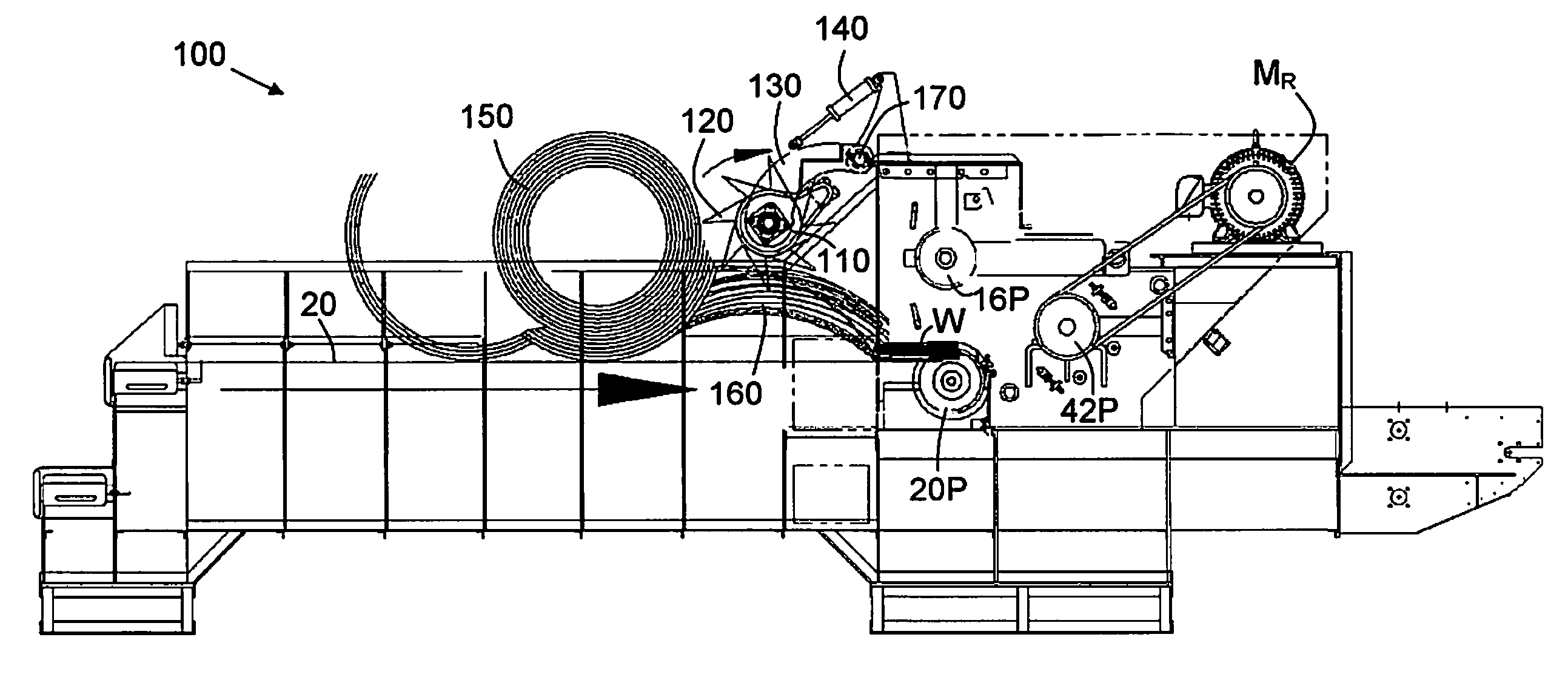
[0035]An auxiliary powerfeed is designed to assist a horizontal grinder to process materials that are bound, packaged, or otherwise joined together into solid form, including round and square agricultural bales, baled recyclables (such as plastic bottles), and gaylord boxes. Other feedstocks for which it may provide advantages include cabinets, crates, and other objects constructed by nailing or otherwise joining individual members of wood, plastic, or other light materials. The purpose of the auxiliary powerfeed is to separate these materials before they reach the standard powerfeed, thereby increasing the efficiency and efficacy of the standard powerfeed and the grinder as a whole.

[0036]An auxiliary powerfeed is disclosed, which is designed to work in conjunction with other feeding devices found on a horizontal grinder, which typically include a horizontal feed conveyor and a powerfeed drum. The auxiliary powerfeed features a rotating drum on which are mounted rigid tines (or teet...


PUM


Abstract

An auxiliary powerfeed is disclosed, which is designed to work in conjunction with other feeding devices found on a horizontal grinder, which typically include a horizontal feed conveyor and a powerfeed drum. The auxiliary powerfeed features a rotating drum on which are mounted rigid tines (or teeth) arranged in a staggered pattern. The drum is rotationally mounted within a pivotally mounted lift arm. The lift arm holds the axial shaft of the drum at each end. A set of hydraulic cylinders is mounted to the lift arm, one on each end of the drum. During operation, as a bale or other object comes into contact with the auxiliary powerfeed, the drum automatically lifts until it reaches the top of the object, the limit of its lift path, or a predetermined height that optimizes efficacy for a particular application. In some cases, the auxiliary powerfeed automatically operates differently with different feedstock consistencies. In other cases, the auxiliary powerfeed is set to operate on a predetermined sequence based on feedstock consistency.

Description

CROSS-REFERENCE TO RELATED APPLICATIONS[0001]The present application claims priority under 35 U.S.C §119(e) to provisional application No. 61 / 139,122, filed on Dec. 19, 2008 under the same title. Full Paris Convention priority is hereby expressly reserved.STATEMENT REGARDING FEDERALLY SPONSORED RESEARCH OR DEVELOPMENT[0002]Not ApplicableBACKGROUND OF THE INVENTION[0003]1. Field of the Invention[0004]The present invention is directed to an auxiliary powerfeed and its control system, designed to assist a horizontal grinder that processes materials that are bound, packaged, or otherwise joined together into solid form, such as round and square agricultural bales.[0005]2. Description of the Related Art[0006]Baling of products is common across a wide range of industries because many bulk products are easier to handle and take up less space in a compacted bale form. Common baled materials include agricultural products like hay, straw, and corn stover, as well as waste and recyclable mater...

Claims


Application Information

Patent Timeline
Patent Type & Authority Applications(United States)
IPC IPC(8): B02C23/02B02C25/00
CPCA01F29/005B02C18/16B02C18/225D01G7/04B02C2201/066D01G7/00B02C2018/164
Inventor BRICK, JAMEYBURG, PATRICKLIESER, NICHOLAS
Owner ROTOCHOPPER
Learn More