Aligned multiple emitter package

a technology of emitter package and aligned package, which is applied in the direction of semiconductor devices, semiconductor/solid-state device details, electrical apparatus, etc., can solve the problems of reduced color fidelity, reduced color emission uniformity, and different emission characteristics of leds in some conventional emitter packages, so as to improve current control of the emitter and improve color emission uniformity , the effect of rigid package assembly

Active Publication Date: 2010-06-24
CREE HUIZHOU SOLID STATE LIGHTING
View PDF94 Cites 114 Cited by
  • Summary
  • Abstract
  • Description
  • Claims
  • Application Information

AI Technical Summary

Benefits of technology

[0009]The present invention provides emitter package lead frames, emitter packages and LED screens that provide for improved color emission uniformity at different viewing angles. The present invention also provides emitter packages with that allow for improved current control of the emitters in the packages, rigidity of the package assembly, and waterproof package operation.

Problems solved by technology

The LEDs in some conventional emitter packages suffer from different emission characteristics at different viewing angles.
Conventional emitter packages can also suffer from a perceptible loss of color fidelity with increasing viewing angle.
Additionally, the material of each emitter package and / or the material used to mount each of the LEDs within the packages may have reflective characteristics, which can further decrease color fidelity by creating unwanted light reflection and / or glare.
Emitter packages such as SMDs, whether containing integrated circuits or discrete components such as diodes or power transistors, can generate significant heat, particularly in high power devices.
However, the leads often do not have sufficient mass or exposed surface area to provide effective heat dissipation.
For example, high intensity LEDs that emit light principally in the visible part of the electromagnetic spectrum can generate significant amounts of heat that is difficult to dissipate using such conventional techniques.

Method used


Image

  • Aligned multiple emitter package
  • Aligned multiple emitter package
  • Aligned multiple emitter package

Examples


Embodiment Construction

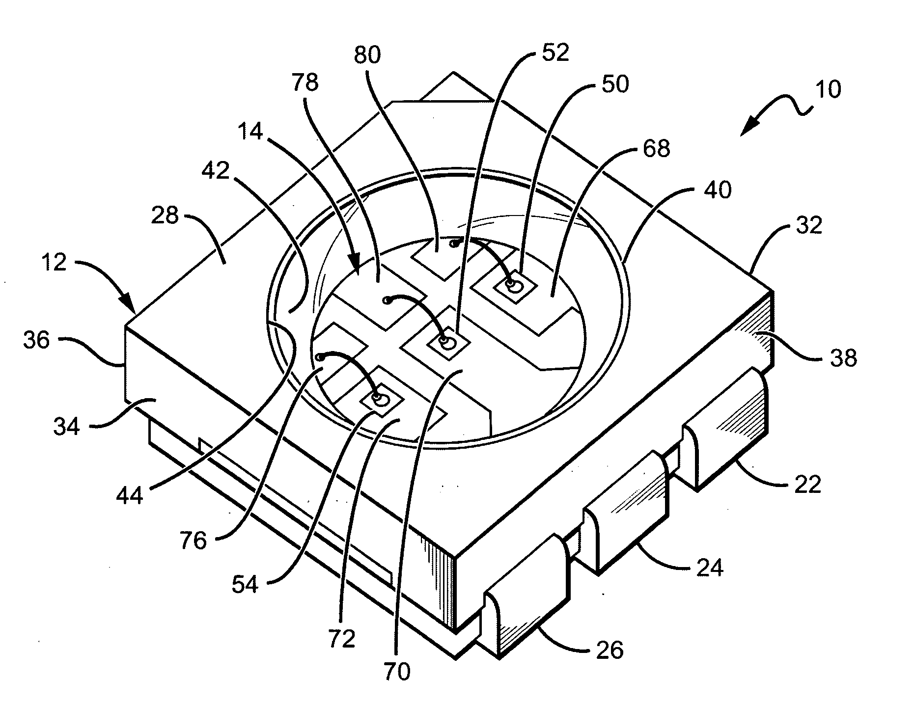
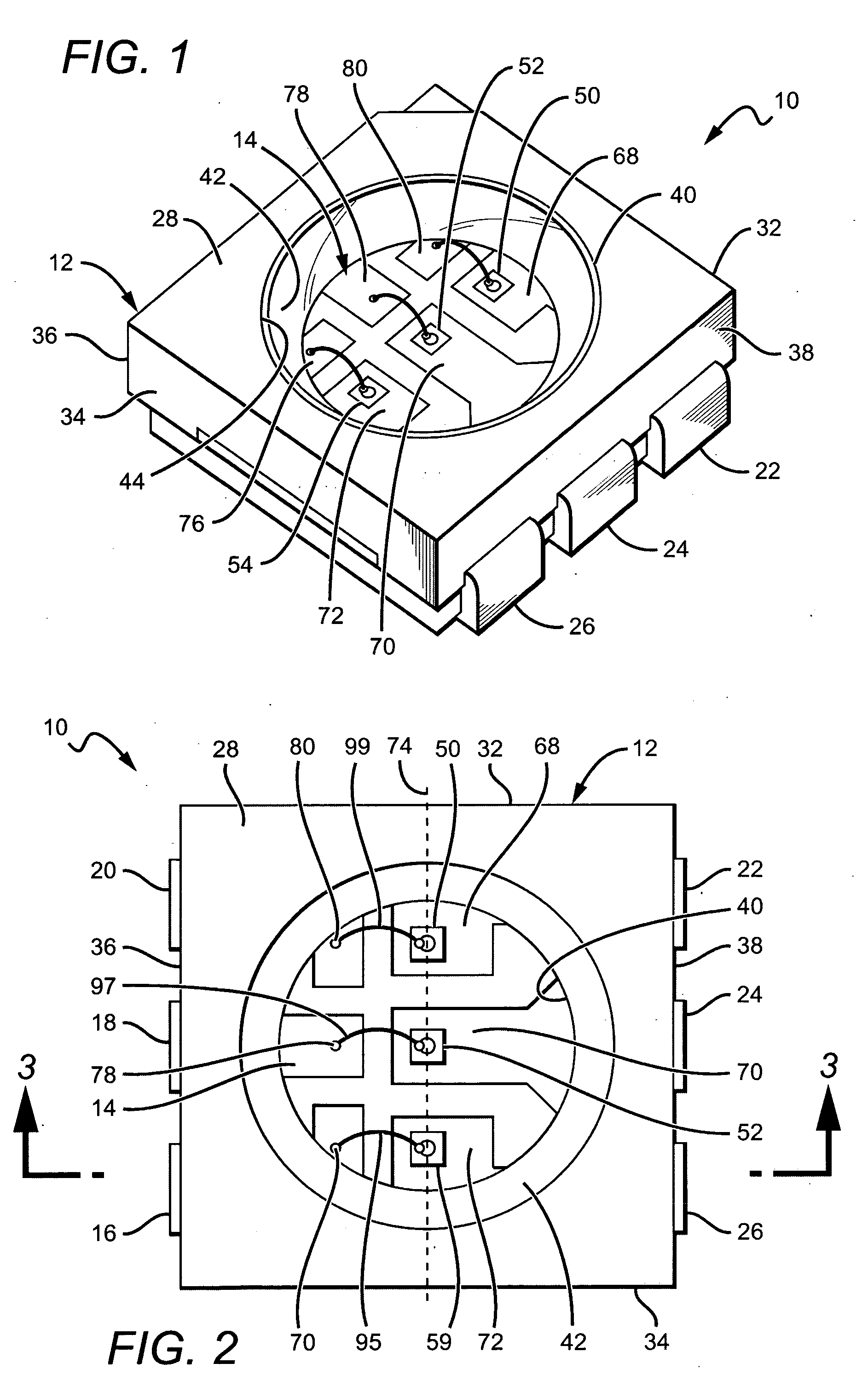
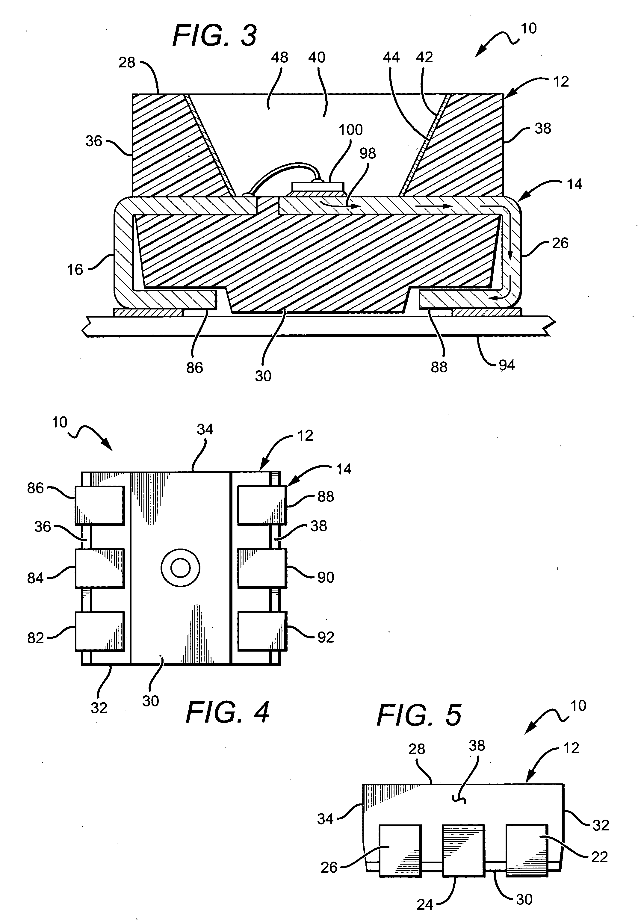
[0031]The present invention provides structures for multi emitter packages that allow the packages to emit light with improved color uniformity at different viewing by linearly aligning the emitters within the package. In one embodiment, the emitters are vertically aligned although it is understood that in different applications the emitters could be horizontally aligned or aligned at an angle. In some embodiments, the packages can also have lead frame structures that allow each of the emitters in the package to be driven by its own electrical signal. This allows for improved control over the color and intensity of light emitted by the emitter package.

[0032]In one embodiment of an emitter package according to the present invention the emitters can comprise red, green and blue emitters that are vertically aligned at or near the centerline of the package so that the viewing angles of the red, green and blue colors coincide with each other. This allows the color of the emitter package ...


PUM


Abstract

A multiple element emitter package is disclosed for increasing color fidelity and heat dissipation, improving current control, increasing rigidity of the package assembly. In one embodiment, the package comprises a surface-mount device a casing with a cavity extending into the interior of the casing from a first main surface is provided. A lead frame is at least partially encased by the casing, the lead frame comprising a plurality of electrically conductive parts carrying a linear array of light emitting devices (LEDs). Electrically conductive parts, separate from parts carrying the LEDs have a connection pad, wherein the LEDs are electrically coupled to a connection pad, such as by a wire bond. This lead frame arrangement allows for a respective electrical signal can be applied to each of the LEDs. The emitter package may be substantially waterproof, and an array of the emitter packages may be used in an LED display such as an indoor and/or outdoor LED screen.

Description

BACKGROUND OF THE INVENTION[0001]1. Field of the Invention[0002]The present invention relates generally to multi emitter packages, and more particularly to surface mount packages having multiple emitters that are aligned to improve emission uniformity.[0003]2. Description of the Related Art[0004]In recent years, there have been dramatic improvements in light emitting diode (LED) technology such that LEDs of increased brightness and color fidelity have been introduced. Due to these improved LEDs and improved image processing technology, large format, full color LED video screens have become available and are now in common use. Large format LED displays typically comprise a combination of individual LED panels providing image resolutions determined by the distance between adjacent pixels or “pixel pitch”.[0005]Outdoor display that may be intended for viewing from greater distances, can have relatively large pixel pitches and usually comprise discrete LED arrays. In the discrete LED ar...

Claims


Application Information

Patent Timeline
Patent Type & Authority Applications(United States)
IPC IPC(8): H01L33/00H01L23/495
CPCH01L23/49861H01L25/0753H01L33/486H01L33/62H01L33/642H01L33/647H01L2224/32245H01L2224/48091H01L2224/48247H01L2224/48465H01L2224/73265H01L2924/00014H01L2924/00012H01L2924/00H01L24/73H01L2924/14
Inventor CHAN, CHI KEUNG ALEXLAU, YUE KWONG VICTORWANG, XUAN
Owner CREE HUIZHOU SOLID STATE LIGHTING
Why Eureka
Try Eureka