

Semiconductor device
- Summary
- Abstract
- Description
- Claims
- Application Information
AI Technical Summary
Benefits of technology
Problems solved by technology
Method used
Image

Examples
first embodiment
[0061]FIG. 7 is a schematic diagram illustrating a semiconductor device in accordance with the inventive concept. The semiconductor device illustrated in FIG. 7 is similar to the semiconductor device illustrated in FIG. 3, except that one of power voltage terminals 20-1 is a DC component power voltage terminal 20-1′, and the semiconductor device illustrated in FIG. 7 additionally comprises an AC component interrupter 5 electrically connected between a power voltage Vcc and DC component power voltage terminal 20-1′. AC component interrupter 5 may comprise a Ferrite or an inductor. In FIG. 7, AC component interrupter 5 is disposed outside of the semiconductor device (i.e., outside of package 2); however, AC component interrupter 5 may be disposed inside package 2 and also may be disposed inside chip 1.
[0062]The semiconductor device of FIG. 7 uses AC component interrupter 5 to interrupt the AC component of power voltage Vcc and applies only the DC component of power voltage Vcc to DC c...
second embodiment
[0065]FIG. 8 is a schematic diagram illustrating a semiconductor device in accordance with the inventive concept. The semiconductor device of FIG. 8 is similar to the semiconductor device of FIG. 7, except that one of ground voltage terminals 20-2 is a DC component ground voltage terminal 20-2′, and the semiconductor device of FIG. 8 additionally comprises an AC component interrupter 6. AC component interrupter 6 may comprise a Ferrite or an inductor. In addition, in the embodiment illustrated in FIG. 8, AC component interrupter 6 is disposed outside of the semiconductor device (i.e., outside of package 2); however, AC component interrupter 6 may be disposed inside package 2 and may also be disposed inside chip 1.
[0066]In the semiconductor device of FIG. 8, AC component interrupter 6 interrupts the AC component of ground voltage GND and applies only the DC component of ground voltage GND to DC component ground voltage terminal 20-2′ (which is one of ground voltage terminals 20-2). T...
fourth embodiment
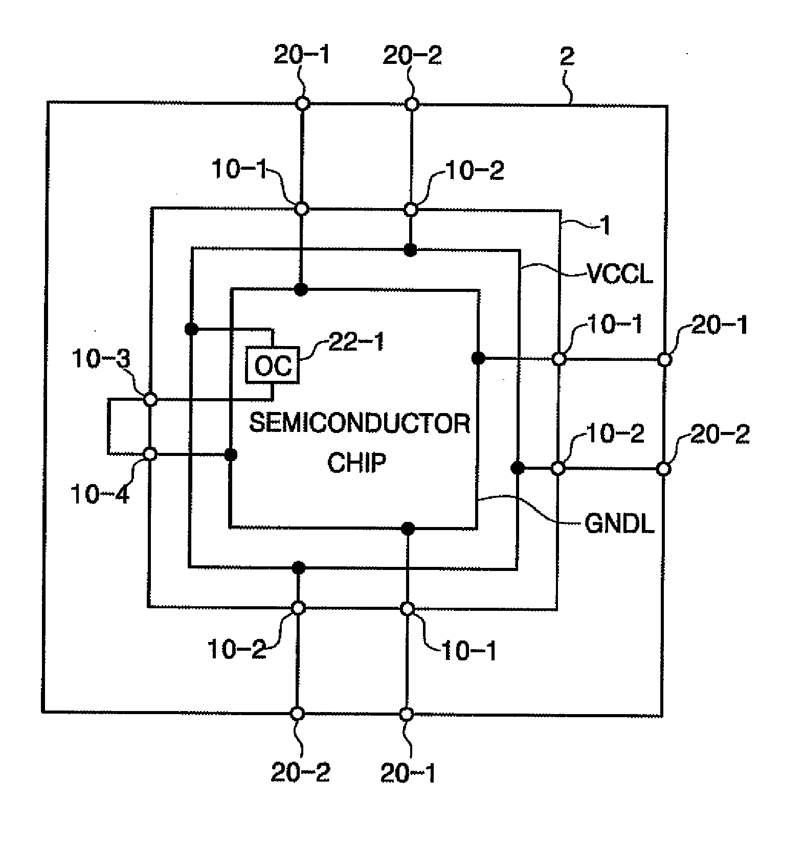
[0079]FIG. 10 is a schematic diagram illustrating a semiconductor device in accordance with the inventive concept. The semiconductor device is similar to the semiconductor device illustrated in FIG. 9, except that on-die capacitor OC 22-1 is not connected between first connection terminal 10-3 and power voltage line VCCL but between first connection terminal 10-3 and ground voltage line GNDL, and second connection terminal 10-4 is not connected to ground voltage line GNDL but with power voltage line VCCL. The semiconductor device of FIG. 10 has different connections than the semiconductor device of FIG. 9 but can reduce power voltage noise identically to the semiconductor device of FIG. 9.
[0080]More specifically, the semiconductor device of FIG. 10 has on-die capacitor OC 22-2, an inductor consisting of a wire, and a resistance of a connection line between power voltage line VCCL and ground voltage line GNDL connected in series between power voltage line VCCL and ground voltage line...
PUM
 Abstract
Description
Claims
Application Information