
Semiconductor integrated circuit, semiconductor system, and electric source voltage control method

Active Publication Date: 2018-07-26
NEC CORP
View PDF10 Cites 1 Cited by
  • Summary
  • Abstract
  • Description
  • Claims
  • Application Information

AI Technical Summary

Benefits of technology

The patent addresses the problem of sudden voltage drops in semiconductor circuits caused by current changes. The invention aims to reduce these voltage drops and improve the stability of the circuit's operation.

Problems solved by technology

Further, accompanying higher integration of a semiconductor integrated circuit, it becomes difficult to predict a peak current quantity due to switching of a circuit element.
In this case, it is concerned that an unexpected voltage noise occurs in the semiconductor integrated circuit, and the voltage noise causes the semiconductor integrated circuit to malfunction.
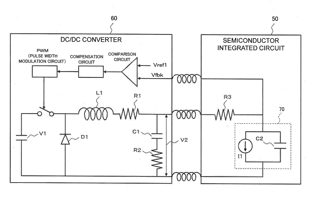
Therefore, the stability operation of the DC / DC converter 60 does not enable the compensation time period up to a time when the voltage drop is compensated to shorten, thus, it is difficult to reduce the voltage noise by shortening the compensation time.
For this reason, it is difficult to reduce the voltage noise due to the sharp current change in the semiconductor integrated circuit, by using this technique.
For this reason, it is difficult to reduce the sharp voltage noise in the semiconductor integrated circuit by using this technique.
Furthermore, since the technique described in reference 3 is a technique for controlling a current, it is difficult to apply the technique to reduction of the sharp voltage noise in the semiconductor integrated circuit.

Method used


Image

  • Semiconductor integrated circuit, semiconductor system, and electric source voltage control method
  • Semiconductor integrated circuit, semiconductor system, and electric source voltage control method
  • Semiconductor integrated circuit, semiconductor system, and electric source voltage control method

Examples


Embodiment Construction

[0038]In the following, example embodiments of the present invention are described in detail with reference to the drawings.

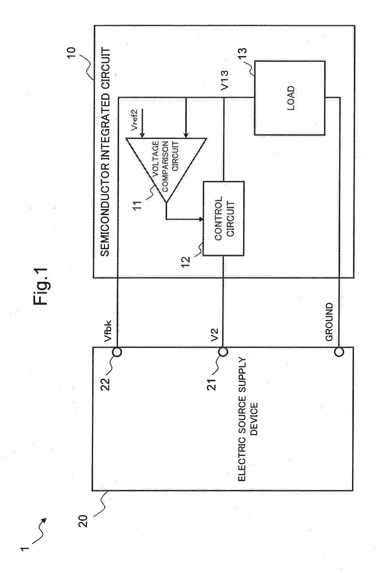
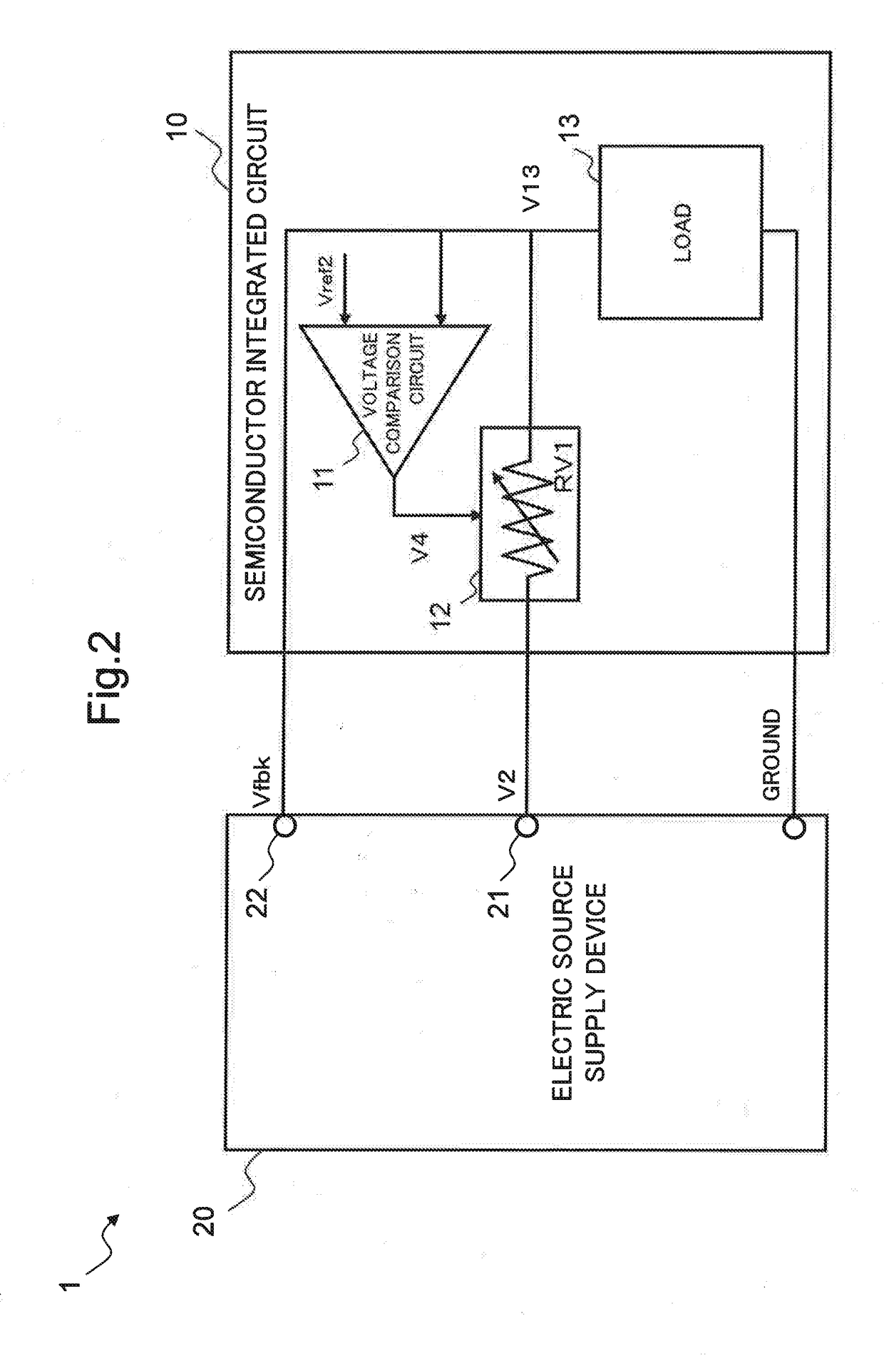
[0039]First, FIG. 1 illustrates a configuration of a semiconductor system 1 as an example embodiment of the present invention. In FIG. 1, the semiconductor system 1 includes a semiconductor integrated circuit 10 and an electric source supply device 20. The semiconductor integrated circuit 10 is connected to an electric source output part 21 and a feedback voltage input part 22 of the electric source supply device 20.

[0040]The electric source supply device 20 outputs an output voltage V2 as an electric source voltage to the semiconductor integrated circuit 10 connected to the electric source output part 21. Further, the electric source supply device 20 controls the output voltage V2 based on a feedback voltage Vfbk input to the feedback voltage input part 22 from the semiconductor integrated circuit 10 and a standard voltage Vref1. Thereby, the electric source v...


PUM


Abstract

A semiconductor integrated circuit includes a voltage comparison circuit and a control circuit. The voltage comparison circuit compares a detection voltage with a reference voltage. The detection voltage is a detected result of an electric source voltage supplied from an electric source supply device supplying the electric source voltage. The reference voltage is set to be lower than a standard voltage used in stabilization control that the electric source supply device performs for stabilizing the electric source voltage. The control circuit performs control of compensating a voltage drop of the electric source voltage when the detection voltage is lower than the reference voltage based on a result of comparison by the voltage comparison circuit.

Description

[0001]This application is based upon and claims the benefit of priority from Japanese Patent Application No. 2017-008111, filed on Jan. 20, 2017, the disclosure of which is incorporated herein in its entirety by reference.TECHNICAL FIELD[0002]The present invention relates to a technique for reducing a sharp voltage noise of electric source voltage inside a semiconductor integrated circuit.BACKGROUND ART[0003]To a semiconductor integrated circuit, an electric source voltage depending on an operation voltage thereof needs to be supplied. For example, as illustrated in FIG. 6, a semiconductor integrated circuit 50 is connected to an electric source output part and a feedback voltage input part of an external direct-current / direct-current (DC / DC) converter 60. The DC / DC converter 60 outputs an output voltage V2 as an electric source voltage to the semiconductor integrated circuit 50. In the semiconductor integrated circuit 50, the electric source voltage supplied to a load 70 is detecte...

Claims


Application Information

Patent Timeline
IPC IPC(8): H04B15/00H03F1/30H02M1/36H01L27/02G01R19/165G11C7/06G11C5/14G06F1/32
CPCH04B15/005H02M1/36G11C5/147G06F1/3296H03F1/305G11C7/06H01L27/02G01R19/16552H01L2924/14G01R31/40
Inventor KOBAYASHI, HIDEAKI
Owner NEC CORP
Learn More