Light emitting device driver circuit and method for driving light emitting device

Inactive Publication Date: 2010-06-24
RICHTEK TECH
View PDF2 Cites 8 Cited by
  • Summary
  • Abstract
  • Description
  • Claims
  • Application Information

AI Technical Summary

Benefits of technology

[0006]In view of the foregoing drawback, the present invention provides a light emitting device driver circuit wi

Problems solved by technology

Such prior art has a drawback that the current source 14 con

Method used


Image

  • Light emitting device driver circuit and method for driving light emitting device
  • Light emitting device driver circuit and method for driving light emitting device
  • Light emitting device driver circuit and method for driving light emitting device

Examples


Example

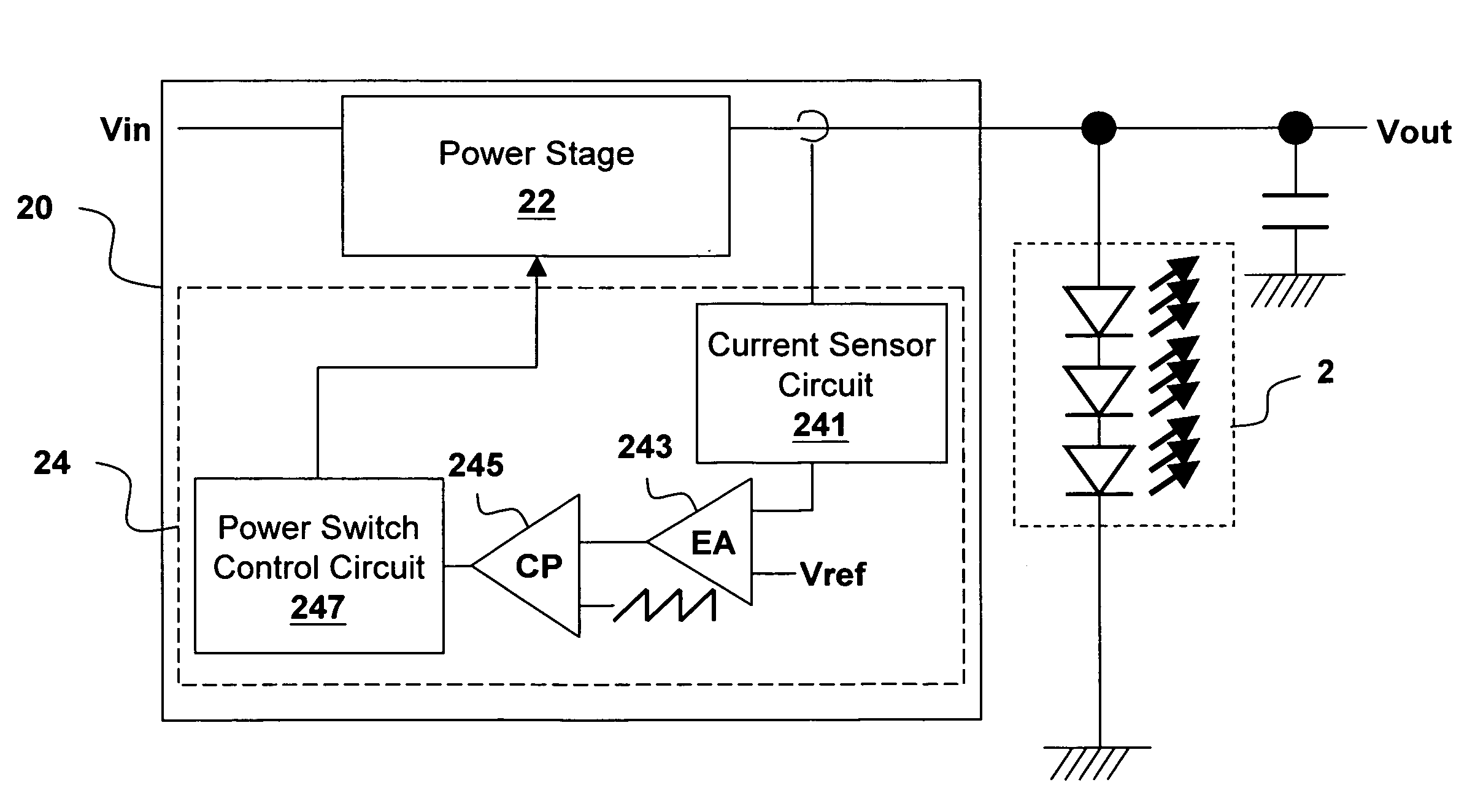
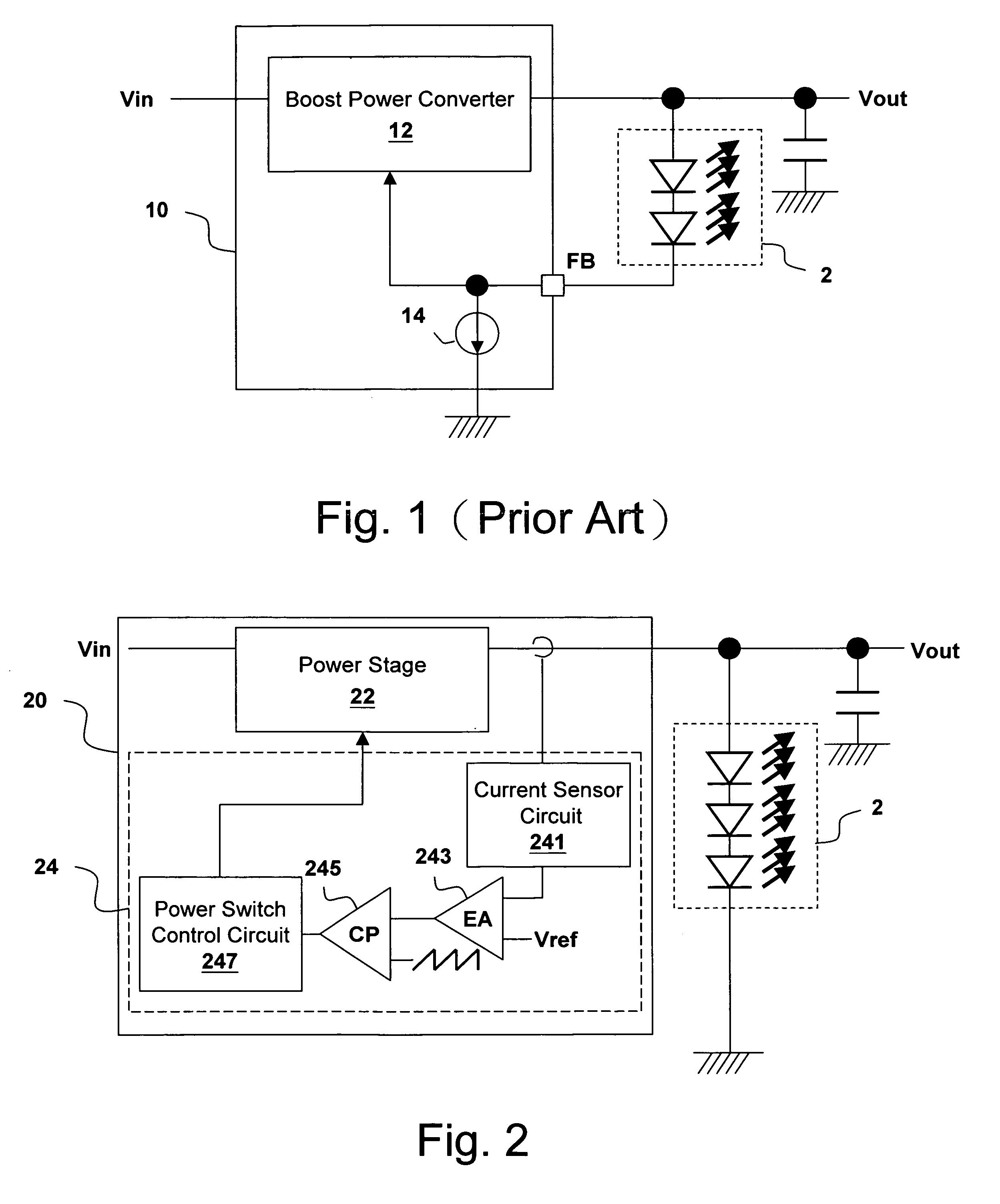
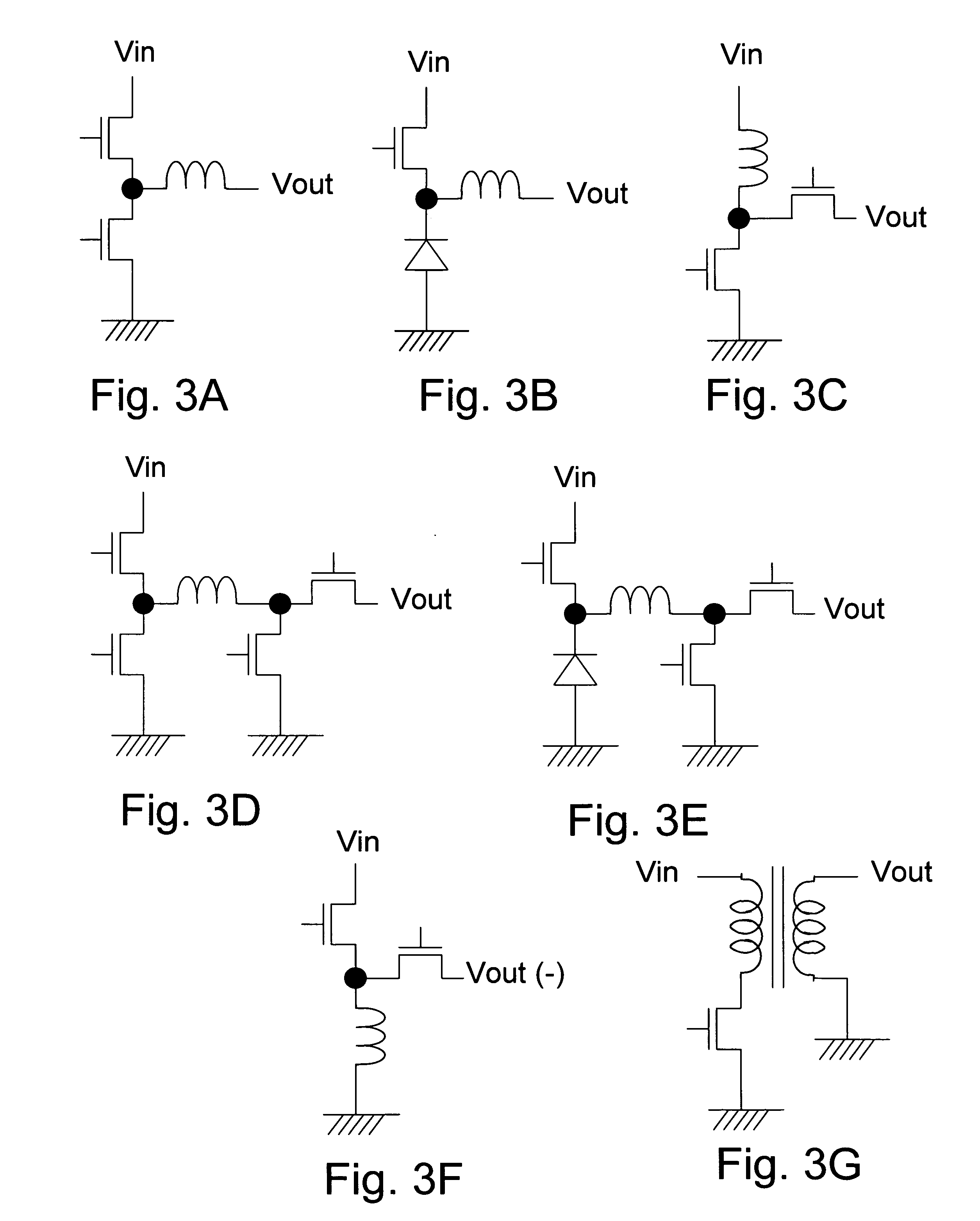
[0018]Please refer to FIG. 2, which shows an embodiment of the present invention by a schematic circuit diagram. The light emitting device driver circuit 20 of the present invention includes a power stage 22 and a control circuit 24. The control circuit 24 controls the power stage 22 to convert an input voltage Vin to an output voltage Vout, and supplies the output voltage Vout to a light emitting device 2. The number of LEDs in the light emitting device 2 can be any number as required, and the LEDs can be connected in series, in parallel, or in parallel-series; what is shown in the drawing is only an example. The power stage 22 for example can be one of: a buck power converter, a boost power converter, a buck-boost power converter, an inverter circuit, and a fly-back power converter, as shown in FIGS. 3A-3G. If the power stage 22 is an inverter circuit as shown in FIG. 3F, the LEDs in the light emitting device 2 should be connected in reverse series, as shown in FIG. 4. The present...


PUM


Abstract

The present invention discloses a light emitting device driver circuit and a method for driving a light emitting device. The circuit comprises: a power stage performing power conversion on an input voltage to supply an output current to one or more light emitting devices; and a control circuit sensing the output current of the power stage to feedback control the power stage accordingly.

Description

BACKGROUND OF THE INVENTION[0001]1. Field of Invention[0002]The present invention relates to a light emitting device driver circuit and a method for driving a light emitting device; particularly, it relates to a light emitting diode (LED) driver circuit having better power utilization efficiency and reduced circuit area, and a method for driving LEDs.[0003]2. Description of Related Art[0004]As shown in FIG. 1, a conventional LED driver circuit 10 usually includes a boost power converter 12 which converts an input voltage Vin to an output voltage Vout and supplies it to a light emitting device 2. The LED driver circuit 10 also includes a current source 14 to control the current flowing through the light emitting device 2. The boost power converter 12 usually includes an error amplifier, a comparator, a power switch, an inductor, a switch control logic circuit, etc., which are well known to persons skilled in this art and are thus omitted here.[0005]Such prior art has a drawback that ...

Claims


Application Information

Patent Timeline
IPC IPC(8): H05B37/02
CPCH05B33/0851H05B33/0815H05B45/10H05B45/39H05B45/375H05B45/3725H05B45/38H05B45/385H05B45/37
Inventor JAN, CHUEH-KUEILIN, SHUI-MU
Owner RICHTEK TECH
Why Eureka
Try Eureka