System and method for thermal limit control

a technology of thermal limit control and pulsing system, which is applied in the direction of pulse manipulation, pulse technique, instruments, etc., can solve the problems of high current, large amount of heat, and significant premature failure, and achieve immediate failur

Active Publication Date: 2010-06-24
LTX CORP
View PDF11 Cites 9 Cited by
  • Summary
  • Abstract
  • Description
  • Claims
  • Application Information

AI Technical Summary

Benefits of technology

[0018]In some embodiments, the method may further include providing an indication of an available ON-time before the maximum allowable ON-time is reached. The method may also include changing the maximum allowable ON-time and a maximum allowable ON-time to OFF time duty cycle in...

Problems solved by technology

High power output stages of electronic systems may source or sink high currents and generate a large amount of heat as a by-product.
If the power component exceeds its acceptable operating range the power component may become thermally overstressed, a situation that may lead to significant premature failures or, in some cases, an immediate failure.
In some cases, pre-loaded tables stored within the automated testing system may set the safe operating conditions and limit the output to an acceptable level.
However, this approach has not always yielded sufficiently accurate results as the generated heat has a thermal lag and will continue to rise even when the VI instrument is turned off to cool.
This may lead to excessive temperature.
In this case, the output stage may be turned off to allow for cooling a...

Method used


Image

  • System and method for thermal limit control
  • System and method for thermal limit control
  • System and method for thermal limit control

Examples


Embodiment Construction

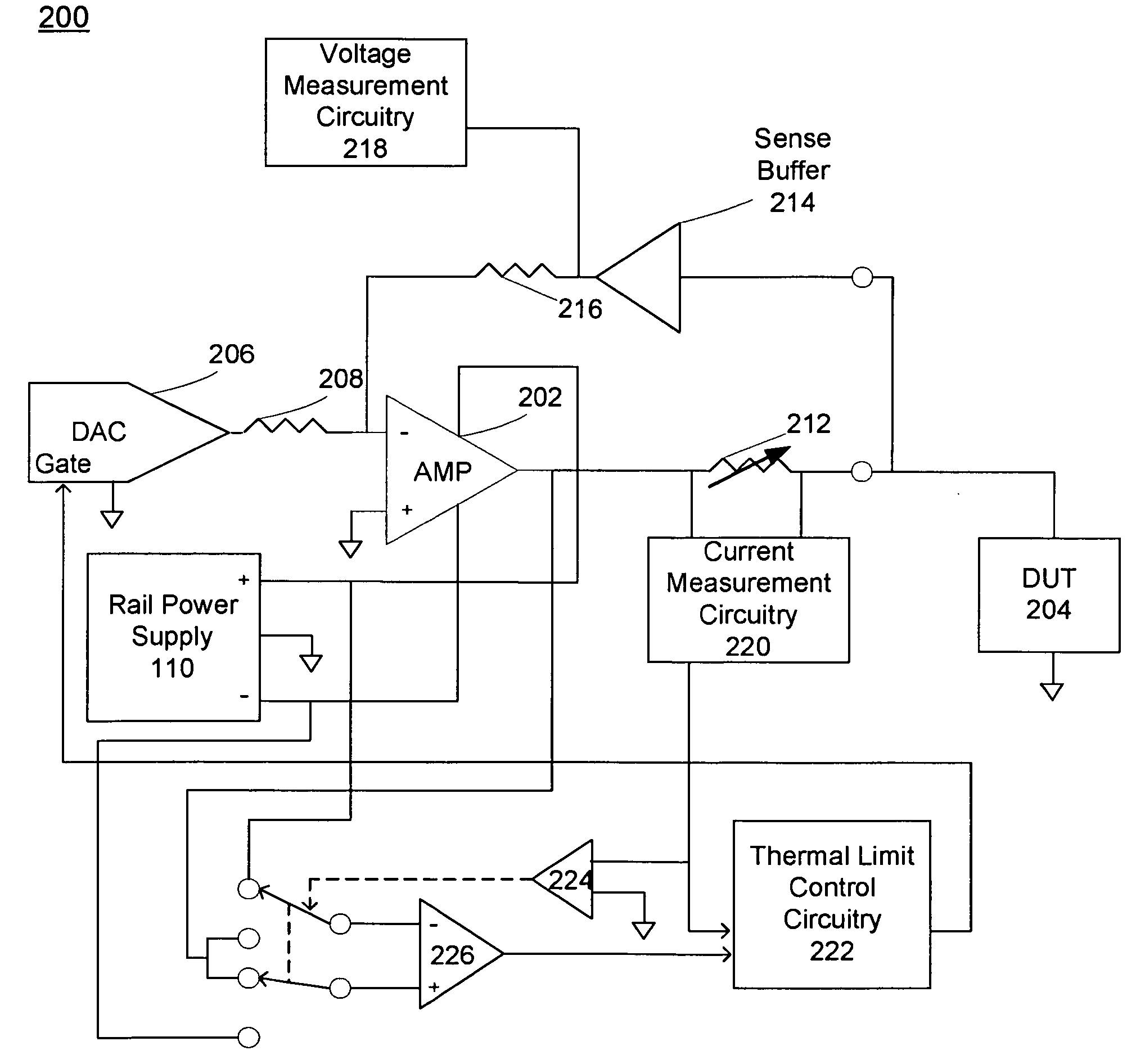
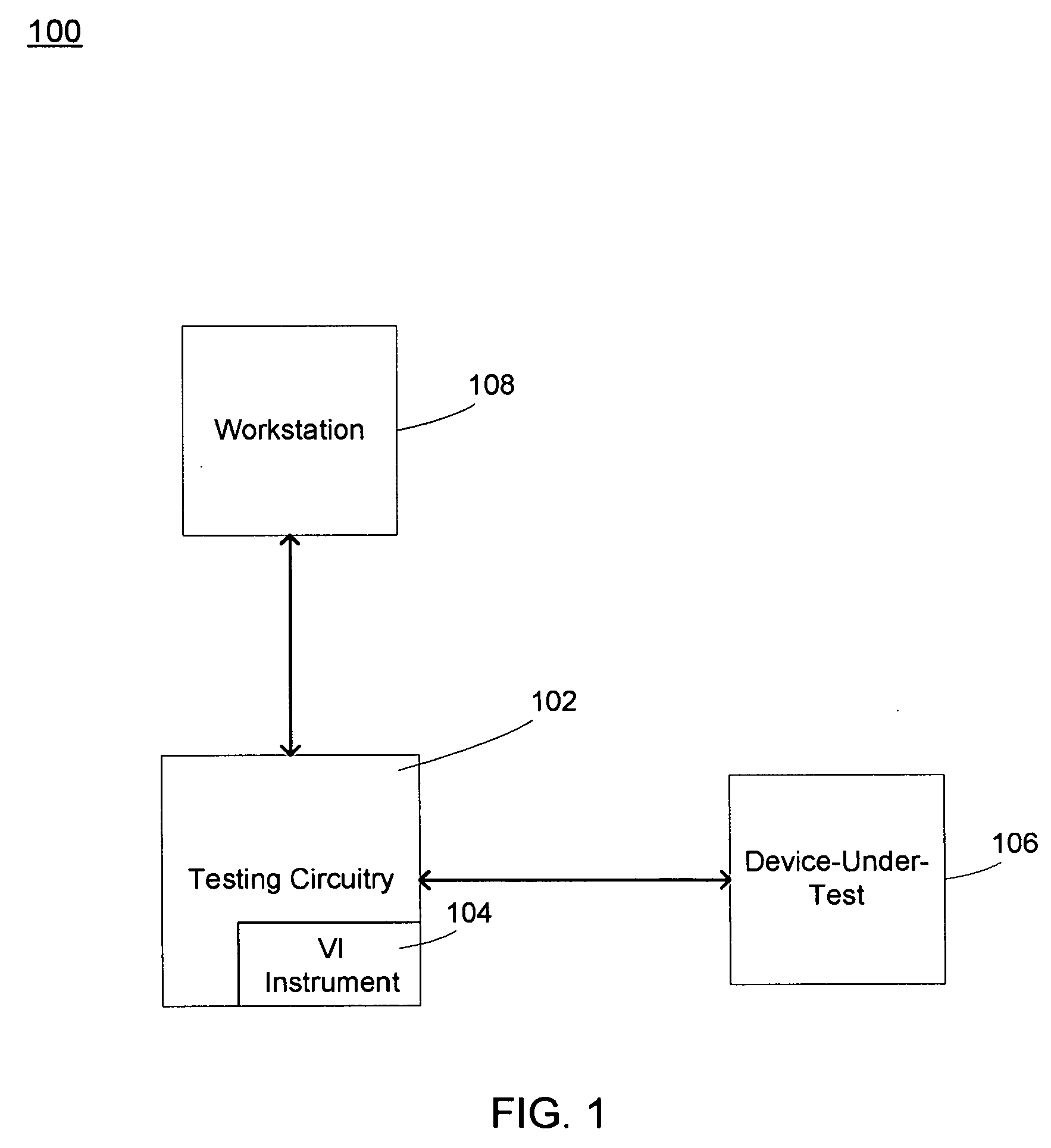
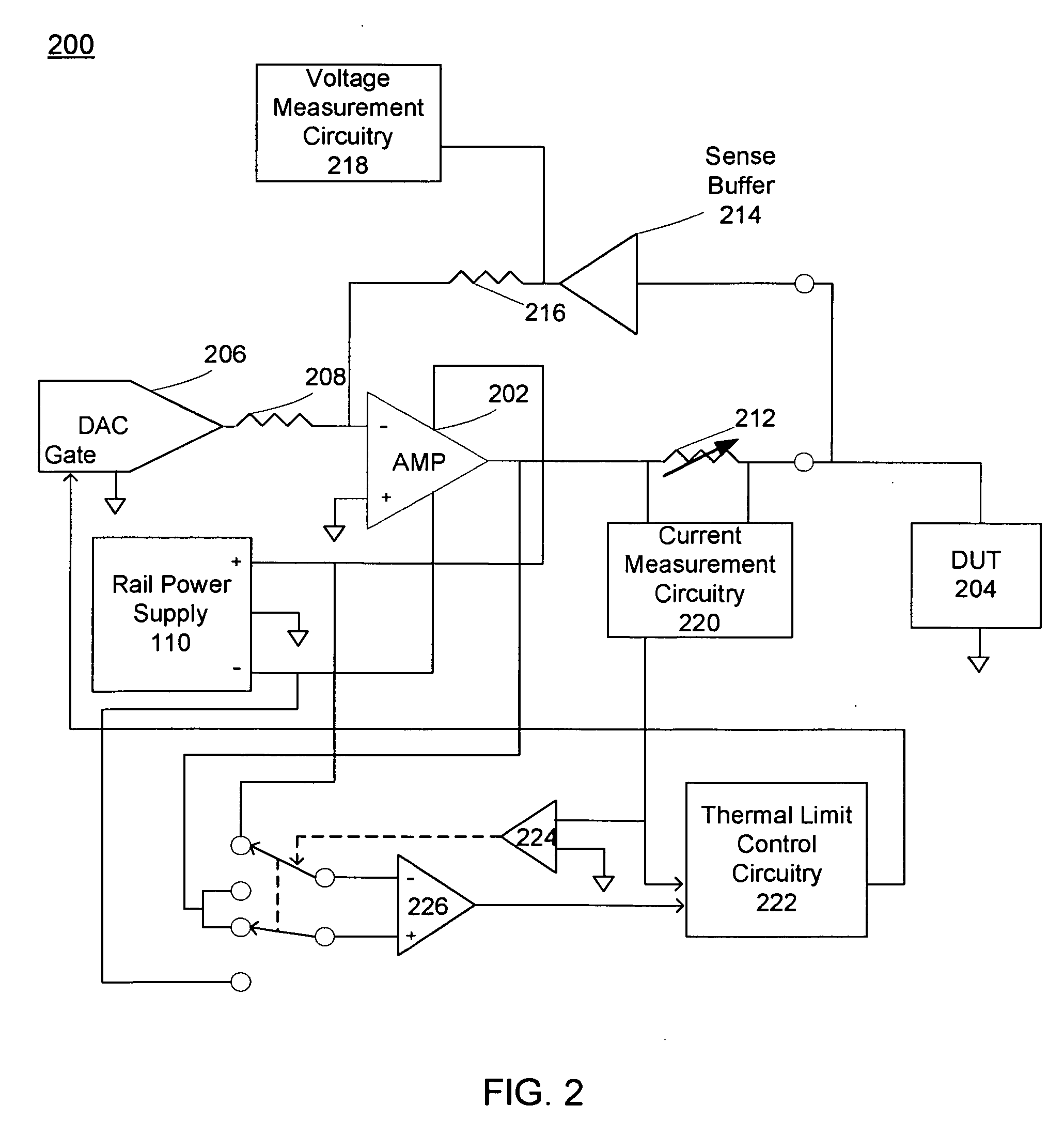
[0032]Referring to FIG. 1, a testing system 100 including testing circuitry 102 having voltage / current (VI) instrument 104 is shown. Testing circuitry 102 may be coupled to device-under-test (DUT) 106, and at least one workstation 108. In some embodiments, testing circuitry 102 may be configured to perform testing upon a number of different devices configured for a variety of applications. Some of these applications may include, but are not limited to, wireless radio frequency (RF), automotive, power management, baseband communications, datacomm, digital-to-analog and analog-to-digital converters. The DUT may be an integrated circuit (IC) and / or any other type of electrical circuitry.

[0033]As used in any embodiment described herein, the term “circuitry” may comprise, for example, singly or in any combination, hardwired circuitry, programmable circuitry, state machine circuitry, and / or firmware that stores instructions executed by programmable circuitry. It should be understood at th...


PUM


Abstract

This disclosure relates to a system and method for pulse generation. A system in accordance with the present disclosure may include a power dissipating element configured to receive power from a power source. At least one of the power source and the power dissipating element may be configured to generate a first signal. The system may further include a measuring instrument in communication with the power source. The measuring instrument may be configured to measure the first signal and to provide an input corresponding to a measured signal to a duty cycle limiter. The system may also include a pulse controller operatively connected to the power source. The pulse controller may be configured to control a duty cycle of the first signal and to receive a second signal from the duty cycle limiter. The pulse controller may be configured to disable at least one of the power source and the power dissipating element if the duty cycle limiter has determined that a maximum condition has been exceeded. Other embodiments are also within the scope of the present disclosure.

Description

TECHNICAL FIELD [0001]This disclosure relates to temperature control of a pulsing system and, more particularly, to thermal limit control using a duty cycle limiter.BACKGROUND [0002]High power output stages of electronic systems may source or sink high currents and generate a large amount of heat as a by-product. A variety of different techniques have been employed to keep the operating temperature of electronic devices within an acceptable range. For example, some systems may use heat sinks on the power components or may supply additional air flow in an effort to decrease the temperature. If the power component exceeds its acceptable operating range the power component may become thermally overstressed, a situation that may lead to significant premature failures or, in some cases, an immediate failure.[0003]Generally, before an electronic device (e.g., an integrated circuit (IC)) is deemed satisfactory, the device is subjected to substantial testing. In some cases, this testing may...

Claims


Application Information

Patent Timeline
IPC IPC(8): H03K3/017G01R19/00
CPCG01R31/2839
Inventor PERKINS, PHILIP EARLELIMOGES, JR., STEPHEN FREDERICKYAN, XIAOMINMCGINLEY, JAMES WILLIAMTHERRIEN, ROGER HENRY
Owner LTX CORP
Why Eureka
Try Eureka