Controller of driver for vehicle

a controller and vehicle technology, applied in the direction of batteries/cells, propulsion, instruments, etc., can solve the problems of inability to provide a power transmission mechanism, hybrid vehicle drive system has a risk of deterioration of fuel economy, and the temperature is considerable, so as to achieve the effect of simple construction, simple construction, and continuous-variable transmission portion operating efficiency

Active Publication Date: 2011-10-11
TOYOTA JIDOSHA KK
View PDF24 Cites 3 Cited by
  • Summary
  • Abstract
  • Description
  • Claims
  • Application Information

AI Technical Summary

Benefits of technology

According to the present invention there is provided a control apparatus for (a) a vehicular drive system including a continuously-variable transmission portion operable as an electrically controlled continuously variable transmission and having a differential mechanism operable to distribute an output of an engine to a first electric motor and a power transmitting member, and a second electric motor disposed in a power transmitting path between the power transmitting member and a drive wheel of a vehicle, the control apparatus being characterized by comprising (b) a differential limiting device provided in the differential mechanism and operable to limit a differential function of the differential mechanism, for limiting an operation of the continuously-variable transmission portion as the electrically controlled continuously variable transmission, and (c) electric-energy restriction control means for placing the differential mechanism in a non-differential state or placing the differential limiting device in a partially power transmitting state, to thereby restrict an amount of electric energy transmitted through the continuously-variable transmission portion, when the amount of transmission of the electric energy through the continuously-variable transmission portion operating as the electrically controlled continuously variable transmission has increased to a predetermined thermal limit.
Preferably, a transmission portion is provided in the power transmitting path between the power transmitting member and the drive wheel. In this case, the vehicular drive system has an overall speed ratio defined by a speed ratio of the differential portion and a speed ratio of the transmission portion, and the vehicle drive force is obtained over a wide range of the speed ratio, owing to a change of the speed ratio of the transmission portion, so that the operating efficiency of the differential portion operating as the electrically controlled continuously variable transmission is further improved. Where the second electric motor is connected to the power transmitting member, and the transmission portion is a speed reducing transmission the speed ratio is higher than 1, the output torque of the second electric motor may be made lower than the torque of the output shaft of the transmission portion, so that the required size of the second electric motor can be reduced. It is noted that the differential portion placed in the continuously-variable shifting state and the transmission portion cooperate to constitute a continuously variable transmission, and the differential portion placed in the non-continuously-variable shifting state and the transmission portion cooperate to constitute a step-variable transmission.

Problems solved by technology

However, there is not available a power transmitting mechanism which has advantages of both of those two devices.
Further, the hybrid vehicle drive system has a risk of deterioration of the fuel economy in some running condition of the vehicle such as a high-speed running, due to the conversion of a portion of the engine output into an electric energy subsequently used for driving the drive wheels.
A similar problem exists where the above-described power transmitting mechanism is a continuously variable transmission such as a transmission the speed ratio of which is electrically variable, for instance, a so-called “electric CVT”.
Such a high-load low-speed running of the vehicle continued for a long time may cause a considerable rise of the temperatures of the first and second electric motors due to an increase of the amount of electric energy, and an increase of loads of components associated with the electric path for transmission of the electric energy generated by the first electric motor to the second electric motor, which converts the electric energy into a mechanical energy.
Those temperature rise and increase of the loads give rise to deterioration of the function and durability of the components associated with the electric path which includes the first and second electric motors.
Meeting these requirements may cause increases of the sizes and weights of the components of the cooling system and the components associated with the electric path, unfavorably leading to an increase of the cost of manufacture of the vehicular drive system.

Method used


Image

  • Controller of driver for vehicle
  • Controller of driver for vehicle
  • Controller of driver for vehicle

Examples


embodiment 1

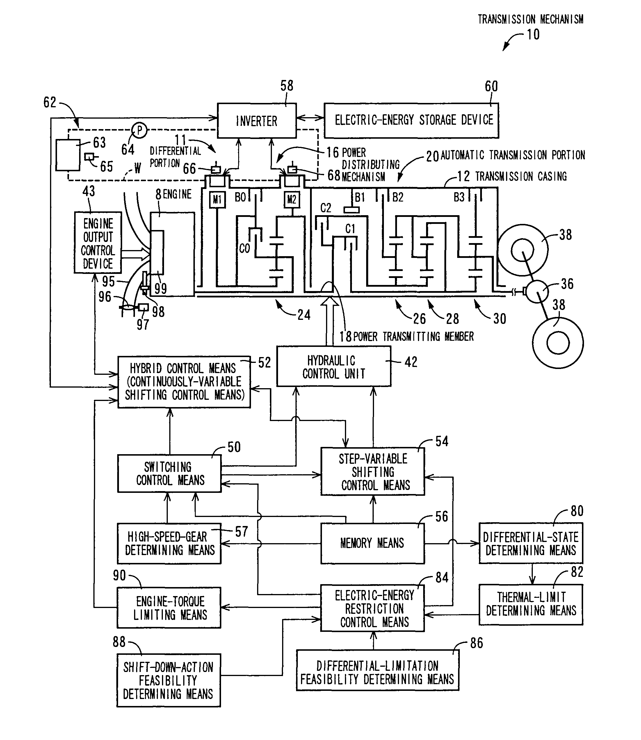
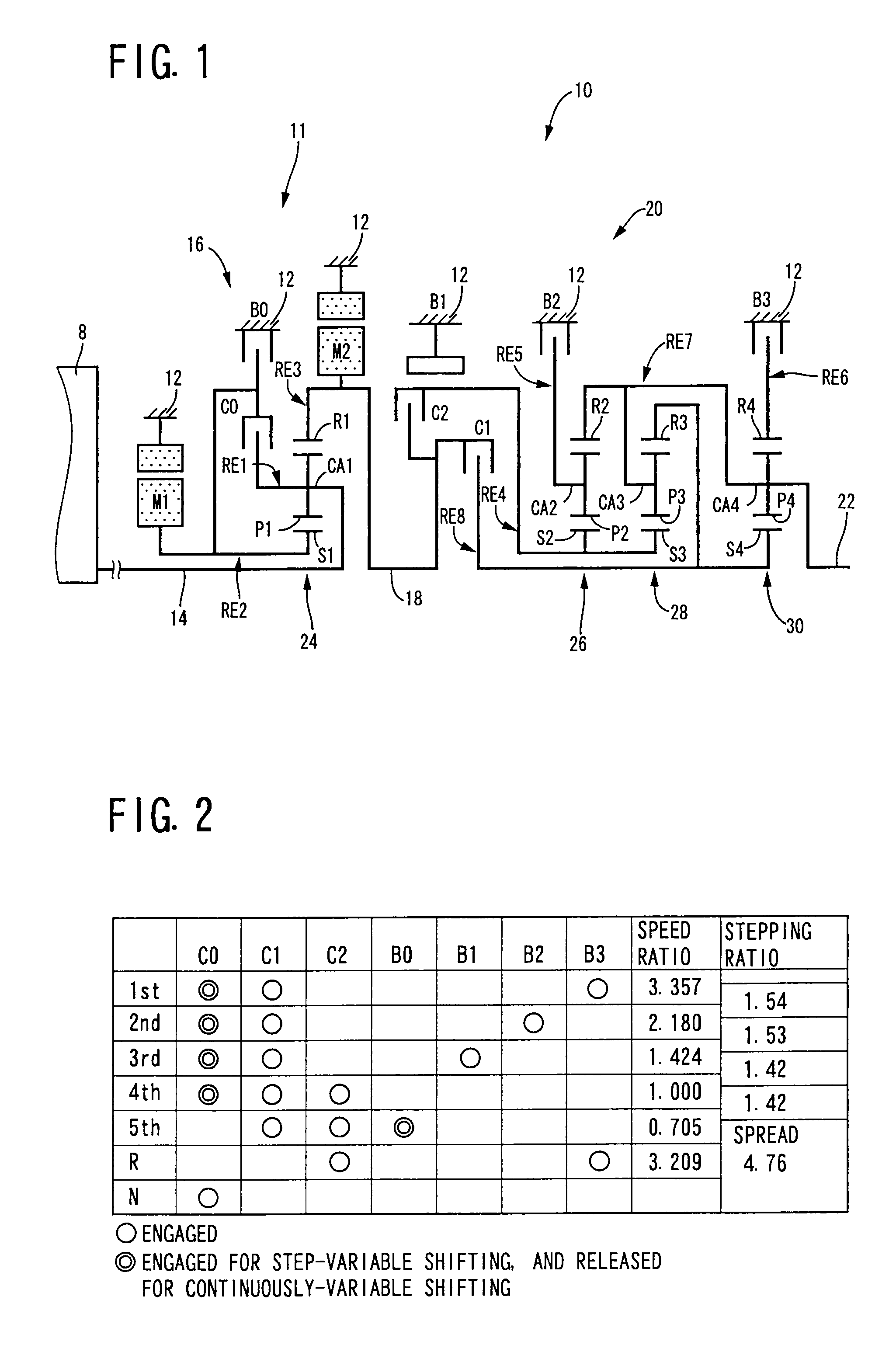
Referring to the schematic view of FIG. 1, there is shown a transmission mechanism 10 constituting a part of a drive system for a hybrid vehicle, which drive system is controlled by a control apparatus according to one embodiment of this invention. In FIG. 1, the transmission mechanism 10 includes: an input rotary member in the form of an input shaft 14; a continuously-variable transmission portion in the form of a differential portion 11 connected to the input shaft 14 either directly, or indirectly via a pulsation absorbing damper (vibration damping device) not shown; a transmission portion functioning in the form of an automatic transmission portion 20 disposed in a power transmitting path between the differential portion 11 and drive wheels 38 of the vehicle, and connected in series via a power transmitting member 18 (power transmitting shaft) to the differential portion 11 and the drive wheels 38; and an output rotary member in the form of an output shaft 22 connected to the au...

embodiment 2

In the preceding embodiment, the thermal-limit determining means 82 is arranged to make the determination as to whether the amount of the electric energy transmitted through the electric path has increased to the thermal limit, by determining whether at least one of the first-electric-motor temperature TEMPM1 and the second-electric-motor temperature TEMPM2 is higher than the predetermined upper limit TEMP1. In the present embodiment, however, the thermal-limit determining means 82 is arranged to make the above-indicated determination, by estimating a value of at least one of the first-electric-motor temperature TEMPM1 and second-electric-motor temperature TEMPM2, (hereinafter collectively referred to as “electric motor temperature TEMPM”) and determining whether the estimated value is higher than the predetermined upper limit TEMP1.

FIG. 12 indicates an example of a change of the electric motor temperature TEMPM. As indicated in FIG. 12, the thermal-limit determining means 82 is con...

embodiment 3

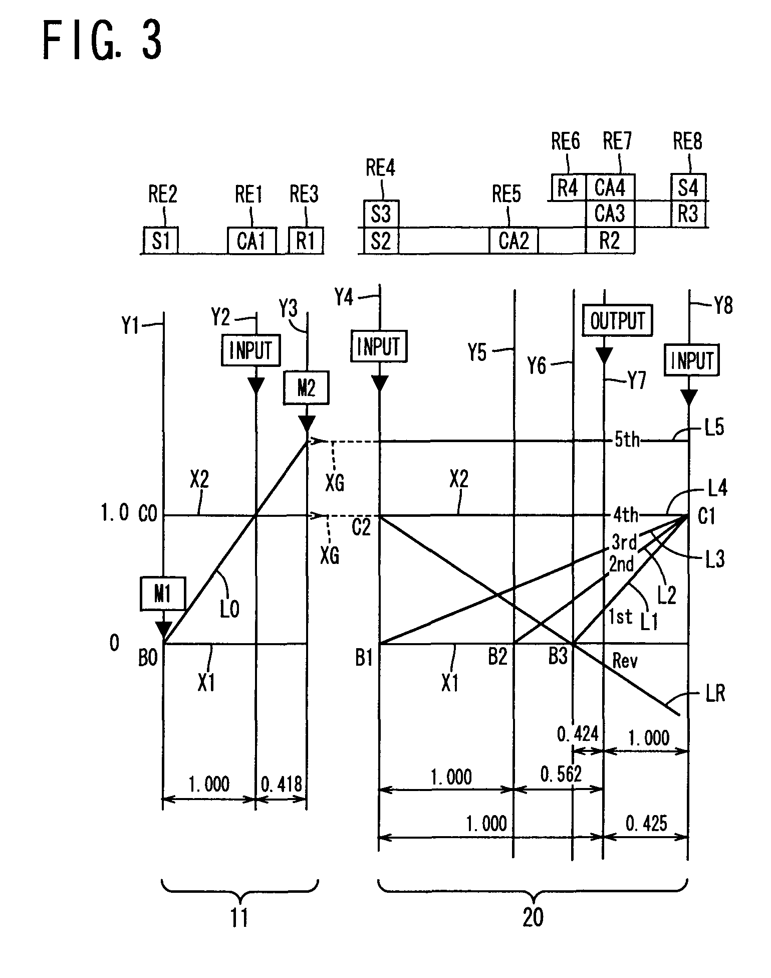
FIG. 14 shows an arrangement of a transmission mechanism 70 in another embodiment of this invention, and FIG. 15 a table indicating a relationship between the gear positions of the transmission mechanism 70 and different combinations of engaged states of the hydraulically operated frictional coupling devices for respectively establishing those gear positions, while FIG. 16 is a collinear chart for explaining a shifting operation of the transmission mechanism 70.

The transmission mechanism 70 includes the differential portion 11 having the first electric motor M1, power distributing mechanism 16 and second electric motor M2, as in the preceding embodiment. The transmission mechanism 70 further includes an automatic transmission portion 72 having three forward drive positions. The automatic transmission portion 72 is disposed between the differential portion 11 and the output shaft 22 and is connected in series to the differential portion 11 and output shaft 22 through the power transm...


PUM


Abstract

A control apparatus for a vehicular drive system arranged to electrically transmit a portion of an output force of an engine through an electric path. The control apparatus is configured to reduce loads of components associated with the electric path and to restrict a temperature rise of the components associated with the electric path, making it possible to reduce the required size of a cooling system. This is accomplished by placing a differential portion in a non-differential state or placing a switching clutch or switching brake in a partially engaged state when electrical energy through the electric path has increased to a thermal limit. As a result, the amount of generated electric energy is reduced, making it possible to restrict the temperature rise of the components associated with the electric path. Accordingly, the cooling system size can be reduced for these components.

Description

TECHNICAL FIELDThe present invention relates to a vehicular drive system including a differential mechanism operable to perform a differential function and an electric motor, and more particularly to techniques for reducing the required size of the electric motor.BACKGROUND ARTThere is known a vehicular drive system including a differential mechanism operable to distribute an output of an engine to a first electric motor and an output shaft, and a second electric motor provided in a power transmitting path between the output shaft of the differential mechanism and vehicle drive wheels. Patent Document 1 discloses an example of such a vehicular drive system in the form of a hybrid vehicle drive system. In this hybrid drive system, the differential mechanism is constituted by a planetary gear set, which has a differential function to mechanically transmit a major portion of a vehicle drive force from the engine to the drive wheels, and to electrically transmit the remaining portion of...

Claims


Application Information

Patent Timeline
Patent Type & Authority Patents(United States)
IPC IPC(8): G06F7/00F16H48/06B60K6/445B60K6/547B60K17/04B60L50/16B60W10/02B60W10/04B60W10/06B60W10/08B60W10/10B60W10/105B60W10/11B60W10/115B60W20/00F02D29/00F02D29/02F16H59/50F16H59/78F16H61/02F16H61/12F16H61/68F16H61/684F16H61/686
CPCB60K6/365B60K6/547B60L11/123B60L11/14B60W10/02B60W10/06B60W10/08B60W10/115B60W30/1843B60K6/445Y02T10/6239B60W20/00B60W30/1846F16H3/728F16H2037/0873F16H2200/0043F16H2200/0047F16H2200/201F16H2200/2012F16H2200/2043F16H2200/2046F16H2200/2048Y02T10/6217Y02T10/6286Y02T10/7077B60L50/61B60L50/16Y02T10/62Y02T10/7072Y02T10/70B60K6/543B60W20/10
Inventor TABATA, ATSUSHITAGA, YUTAKAINOUE, YUJIKAMADA, ATSUSHI
Owner TOYOTA JIDOSHA KK
Why Eureka
Try Eureka