Method for operating multi-domain provider ethernet networks

Inactive Publication Date: 2010-06-24
RPX CLEARINGHOUSE
View PDF6 Cites 11 Cited by
  • Summary
  • Abstract
  • Description
  • Claims
  • Application Information

AI Technical Summary

Benefits of technology

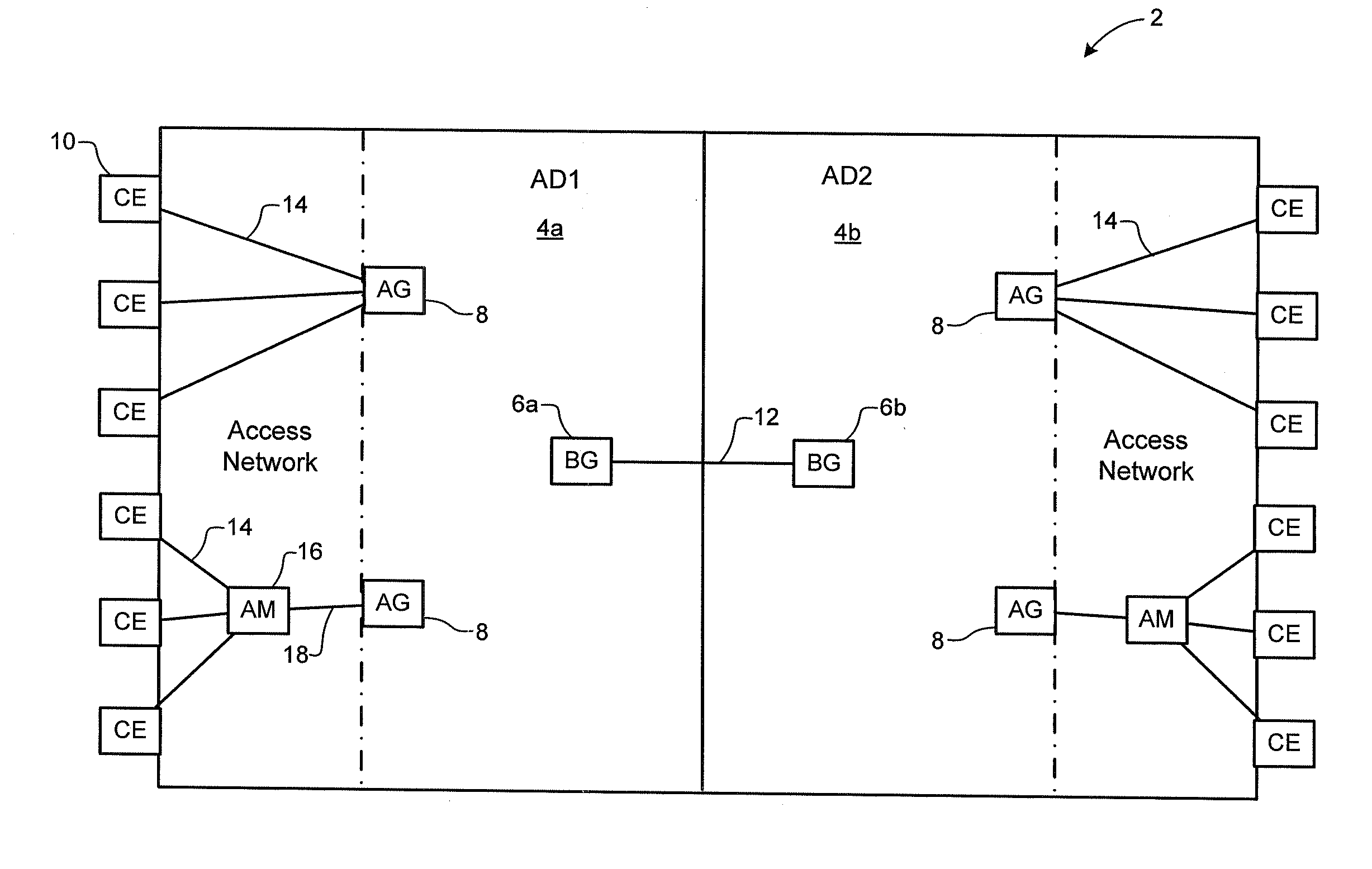
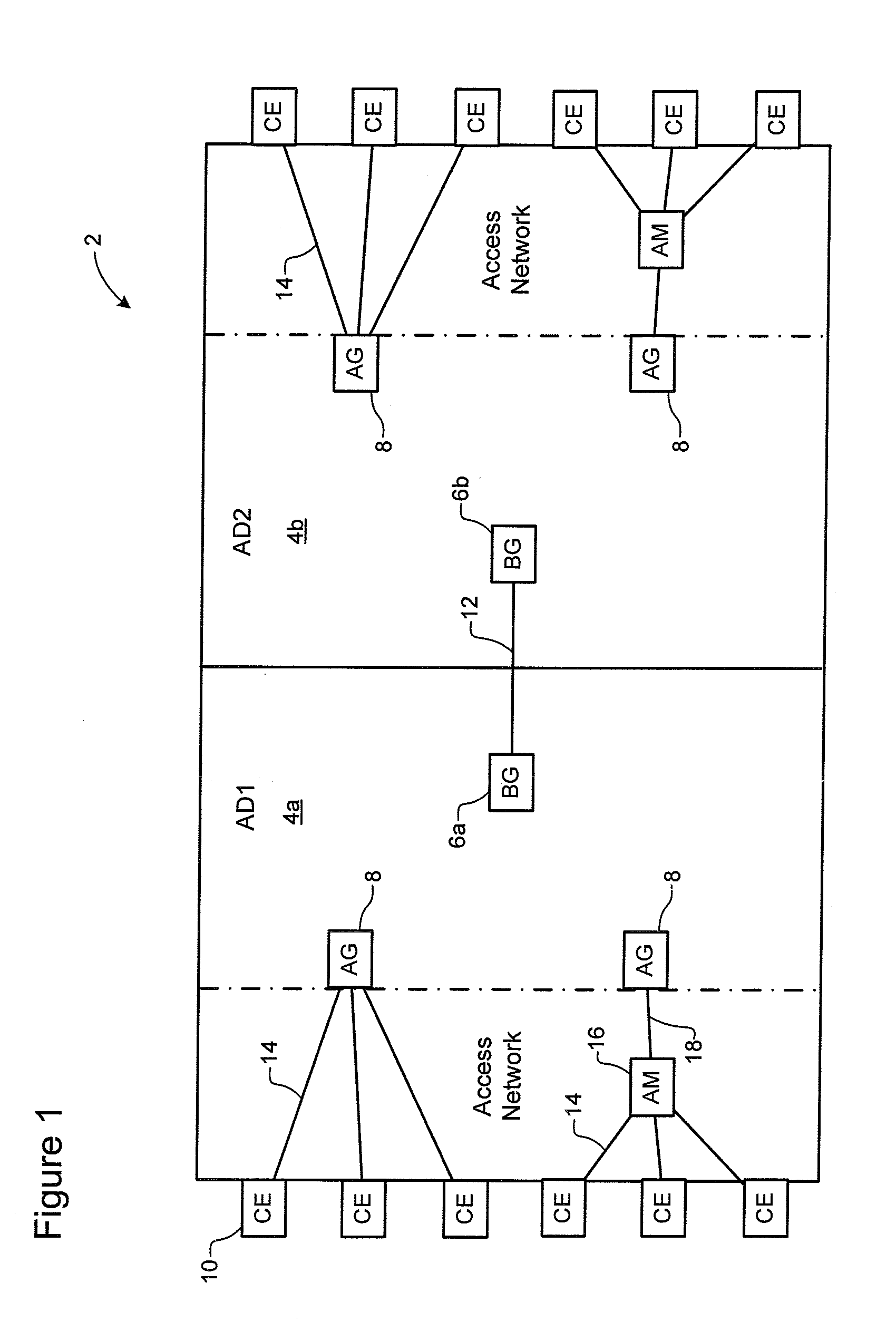
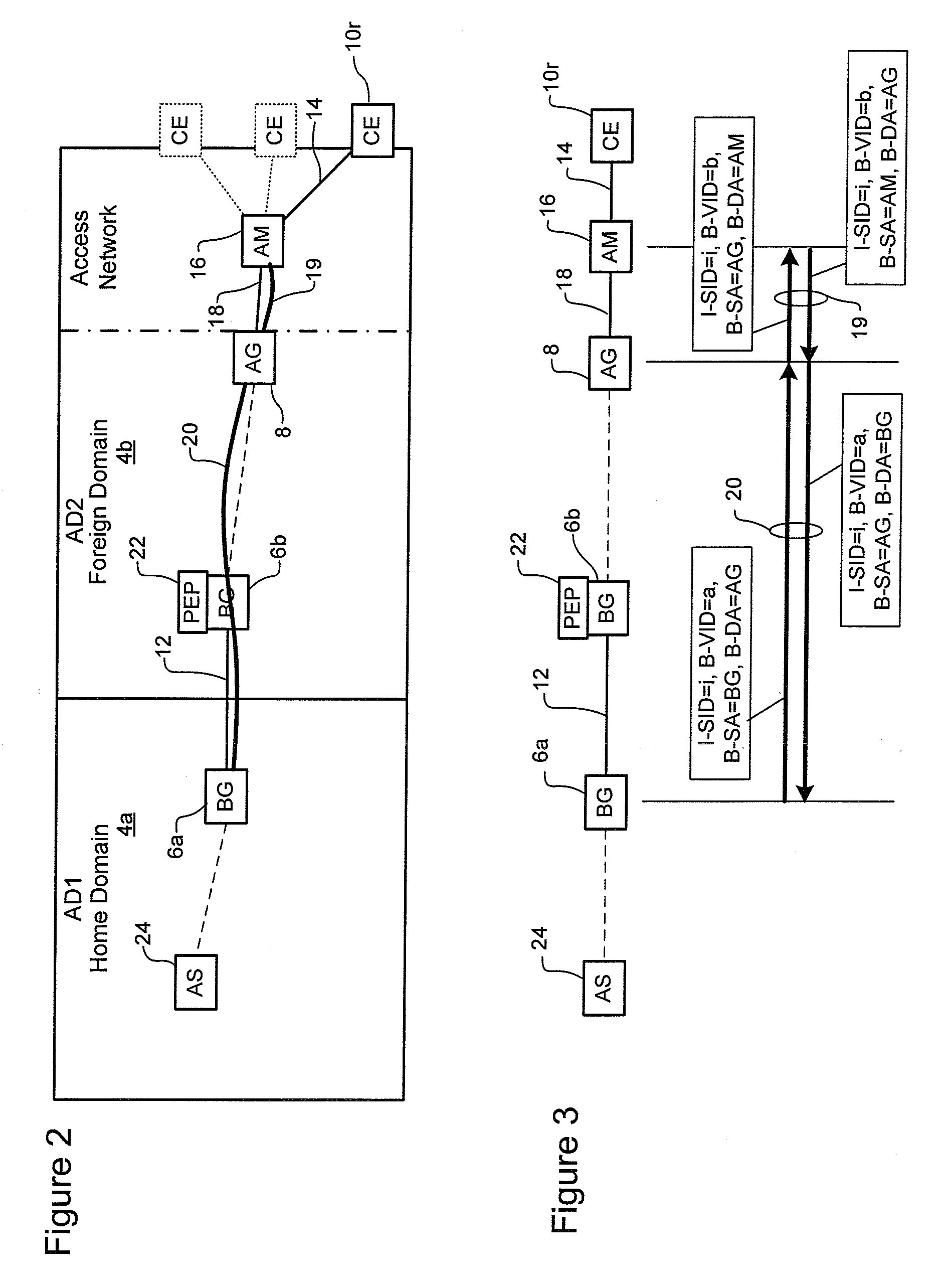
[0011]With this arrangement, the first autonomous domain operates as the “home” domain of a network service instance and controls traffic forwarding related to the network service instance according to the procedures of the specific network service type. Thus, for example, for an ELAN service instance customer Ethernet packets will be forwarded across the first domain based on the customer MAC destination address field in the packet, while for an IP VPN service customer packets will be forwarded across the first domain according to the customer destination IP address. Similarly, the first domain's network operator assumes responsibility for OAM of the service, as well as service-related interactions with the customer. The second domain provides a simple aggregation and trunking service to the first domain, so that subscriber t

Problems solved by technology

However, it often happens that the customer's sites are geographically dispersed to such an extent that they cannot all be directly connected to the same autonomous domain.
However, successful federation of autonomous domains become increasingly complex as the number of member domains increase

Method used


Image

  • Method for operating multi-domain provider ethernet networks
  • Method for operating multi-domain provider ethernet networks
  • Method for operating multi-domain provider ethernet networks

Examples


Example

[0018]It will be noted that throughout the appended drawings, like features are identified by like reference numerals.

DETAILED DESCRIPTION OF PREFERRED EMBODIMENTS

[0019]In very general terms, the present invention provides a method of enabling extension of network services instantiated in a first network domain to remote customer sites in a link state controlled network domain.

[0020]For ease of description, methods in accordance with the present invention will be described herein with reference to a representative embodiment deployed in a Provider Ethernet network domain, such as, for example, any of Provider Link State Bridging (PLSB), Provider Backbone Transport (PBT), Provider Backbone Bridging-Traffic Engineering (PBB-TE), and Provider Backbone Bridging (PBB) network environments. However, while the domain designated below as the foreign domain is required to support Provider Ethernet network technologies, it will be understood that the present invention is by no means limited t...


PUM


Abstract

A method of enabling extension of a network service of a first domain to a remote customer site hosted by an Access Gateway (AG) in a Provider Ethernet domain. In the first domain, the remote customer site is represented as being hosted by a border gateway (BG) connected to the Provider Ethernet domain, such that subscriber packets associated with the network service are forwarded to or from the remote customer site via the BG. In the Provider Ethernet domain, a trunk connection is instantiated through the Provider Ethernet domain between the host AG and the BG. A trunk cross-connection function is installed in the host AG, for transferring subscriber packets associated with the network service between a respective attachment virtual circuit (AVC) through which the remote customer site is connected to the host AG and an extended AVC tunnelled through the trunk connection. A common service instance identifier (I-SID) is used to identify both the AVC between the host AG and the remote customer site and the extended AVC between the host AG and the BG.

Description

CROSS-REFERENCE TO RELATED APPLICATIONS[0001]This is the first application filed for the present invention.MICROFICHE APPENDIX[0002]Not Applicable.TECHNICAL FIELD[0003]The present invention relates to management of traffic forwarding in Provider Ethernet networks, and in particular to methods of extending Virtual Private Network (VPN) network services across a multi-domain Provider Ethernet network.BACKGROUND[0004]Network operators and carriers are deploying packet-switched communications networks in place of circuit-switched networks. In packet-switched networks such as Internet Protocol (IP) networks, IP packets are routed according to routing state stored at each IP router in the network. Similarly, in Provider Ethernet networks, Ethernet frames are forwarded according to forwarding state stored at each Ethernet switch in the network. In this document, the terms “packet” and “packet-switched network”, “routing”, “frame” and “frame-based network”, “forwarding” and cognate terms ar...

Claims


Application Information

Patent Timeline
IPC IPC(8): H04L12/28H04L12/56H04L45/16
CPCH04L12/4658H04L12/4662H04L63/08H04L63/10H04L12/2856H04L63/02H04L12/4633H04L12/66H04L12/46
Inventor CASEY, LIAM
Owner RPX CLEARINGHOUSE
Why Eureka
Try Eureka