
Integrated acoustic transducer in MEMS technology, and manufacturing process thereof

a technology of integrated acoustic transducers and manufacturing processes, applied in the field of microelectromechanical (mems), can solve the problems of reducing the sensitivity of mems microphones, significantly affecting the performance of mems microphones, and deriving residual stresses

Active Publication Date: 2010-06-24
STMICROELECTRONICS SRL
View PDF3 Cites 69 Cited by
  • Summary
  • Abstract
  • Description
  • Claims
  • Application Information

AI Technical Summary

Benefits of technology

The present patent is about a new type of acoustic transducer that can be made using MEMS technology. It includes a cavity in a substrate, a supporting structure, and a membrane that can vibrate to produce sound waves. The membrane is suspended above the cavity and fixed to the substrate using a supporting structure that includes multiple anchorage elements. This design allows for improved sensitivity and accuracy in detecting and producing sound waves.

Problems solved by technology

MEMS microphones of a known type are, however, subject to problems deriving from residual (compressive or tensile) stresses internal to the layer that forms the membrane.
Residual stresses are frequently the cause of mechanical deformations of the membrane, such as warping or buckling, and can significantly affect the performance of the MEMS microphone by reducing the sensitivity.
Even though it is possible to control partially the amount of residual stress in the membrane by means of an appropriate design of the membrane itself and by evaluating the optimal manufacturing conditions, the result obtained is not satisfactory for applications in which a high sensitivity is required.
However, membrane mobile electrodes suspended to the fixed electrode by means of a central anchorage are readily susceptible, during use, to undesirable modes of pitch and roll, which cause a degradation of the performance of the MEMS microphone that uses said mobile electrodes.

Method used


Image

  • Integrated acoustic transducer in MEMS technology, and manufacturing process thereof
  • Integrated acoustic transducer in MEMS technology, and manufacturing process thereof
  • Integrated acoustic transducer in MEMS technology, and manufacturing process thereof

Examples


Embodiment Construction

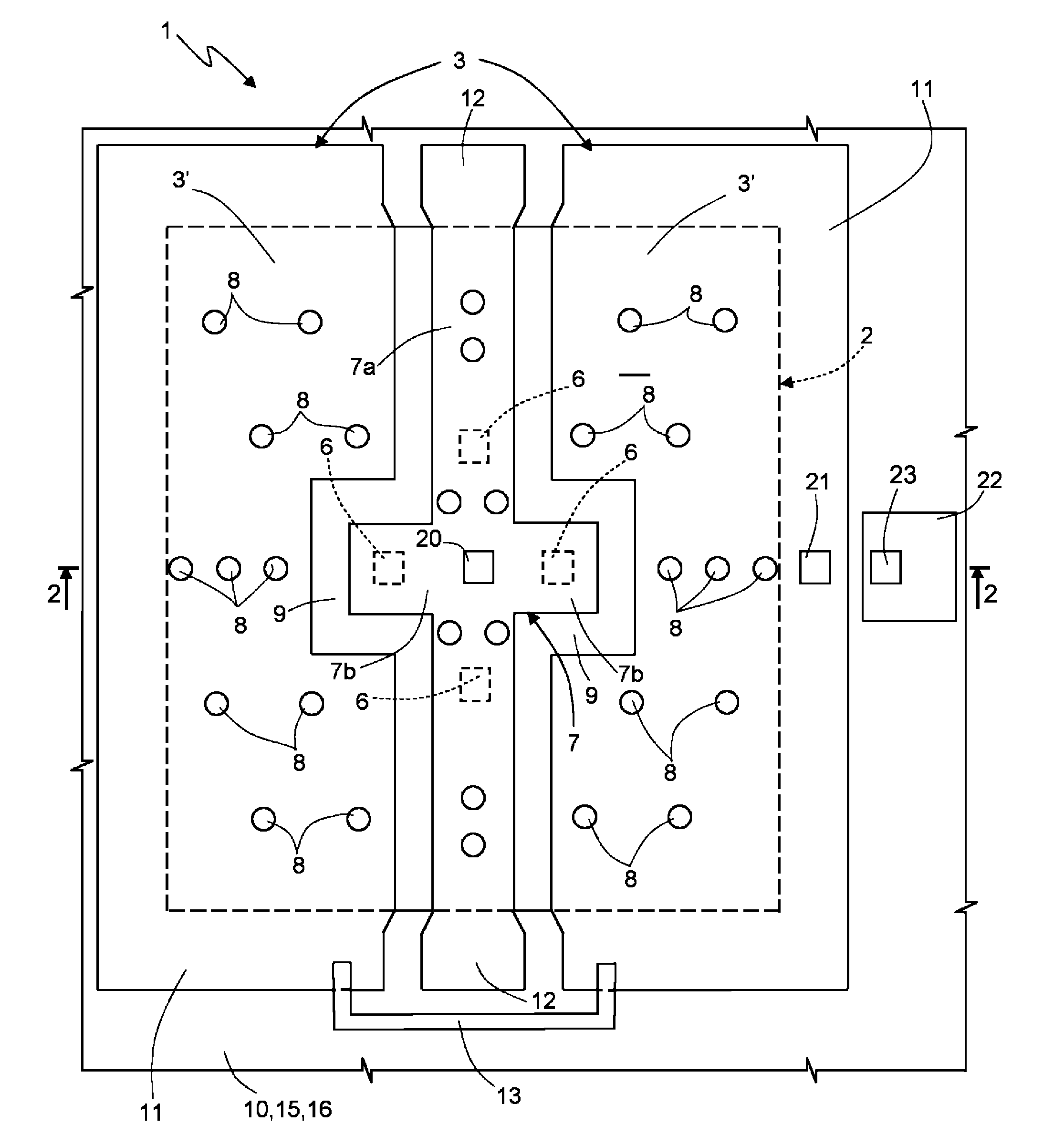
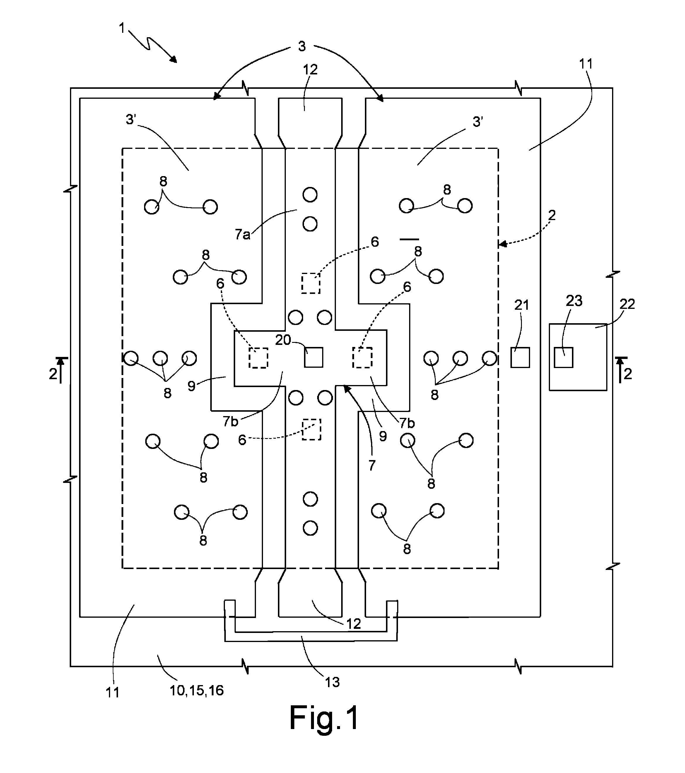
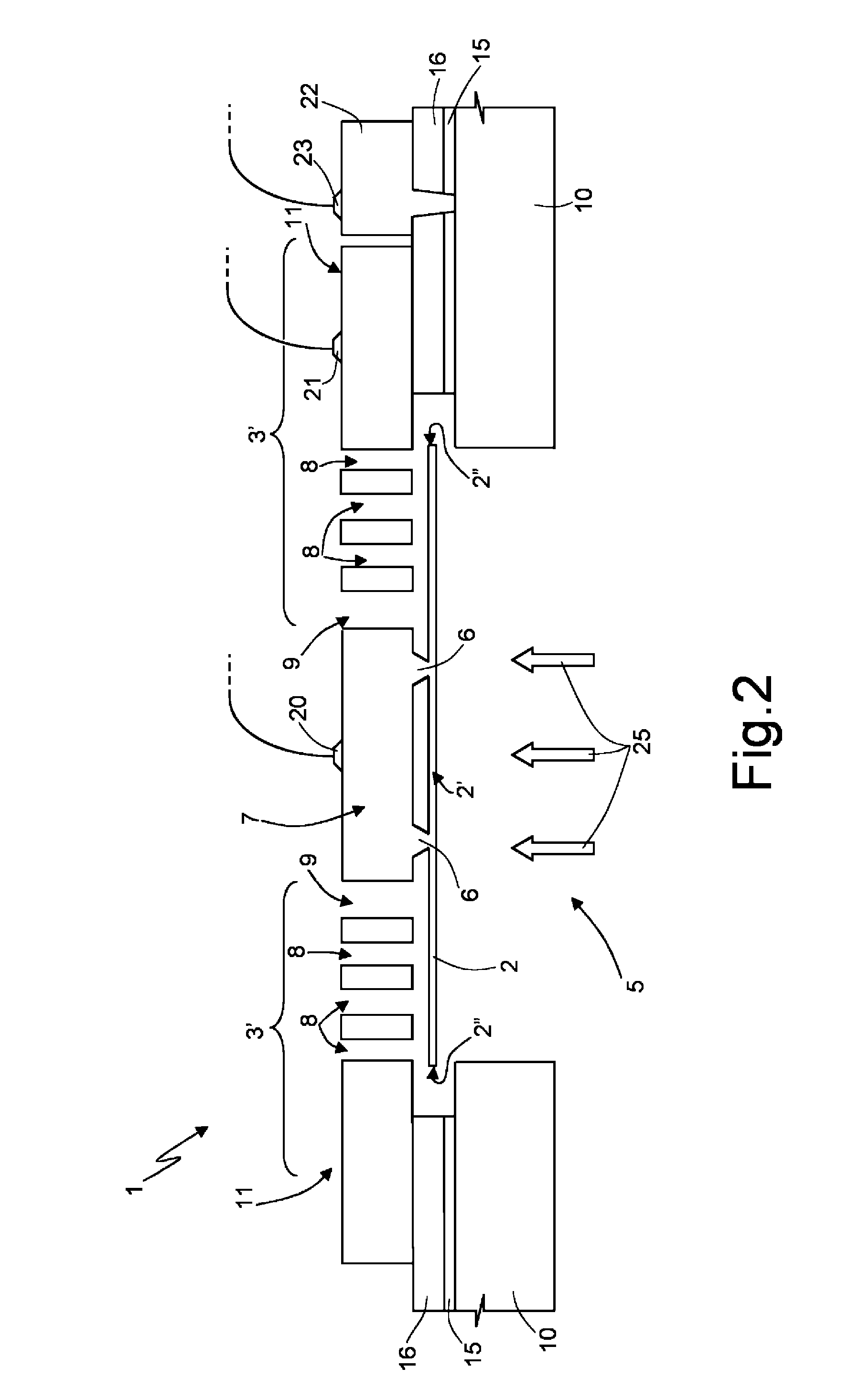
[0024]FIGS. 1 and 2 show, respectively, a top plan view and a cross-sectional view of an assemblage of a membrane and a rigid plate of an integrated acoustic transducer in MEMS technology, for example, a microelectromechanical (MEMS) microphone, according to one embodiment of the present disclosure. For reasons of simplicity, in what follows reference will be made to said assemblage generally as a MEMS microphone 1, even though the electronics of supply and conditioning of the signals, which are, however, necessary, are not illustrated, and even though the description, albeit valid for any acoustic transducer, is limited in particular to a microphone.

[0025]With joint reference to FIGS. 1 and 2, the MEMS microphone 1 is a microphone of a capacitive type and comprises a membrane 2, which is mobile and faces a rigid plate 3 (back plate), which is fixed. The membrane 2 is suspended above a cavity 5 and is supported by one or more supporting beams 7 (only one of which is shown in the fig...


PUM

PropertyMeasurementUnit
thicknessaaaaaaaaaa
thicknessaaaaaaaaaa
thicknessaaaaaaaaaa

Abstract

A MEMS acoustic transducer, for example, a microphone, includes a substrate provided with a cavity, a supporting structure, fixed to the substrate, a membrane having a perimetral edge and a centroid, suspended above the cavity and fixed to the substrate the membrane configured to oscillate via the supporting structure. The supporting structure includes a plurality of anchorage elements fixed to the membrane, and each anchorage element is coupled to a respective portion of the membrane between the centroid and the perimetral edge of the membrane.

Description

BACKGROUND[0001]1. Technical Field[0002]The present disclosure relates to an integrated acoustic transducer in MEMS technology and to the manufacturing process, and in particular to a microelectromechanical (MEMS) microphone of a capacitive type with a suspended-membrane mobile electrode and reduced residual stresses.[0003]2. Description of the Related Art[0004]As is known, an acoustic transducer, for example, a MEMS microphone, of a capacitive type generally comprises a mobile electrode, in the form of a diaphragm or membrane, arranged facing a fixed electrode, to provide the plates of a capacitor. The mobile electrode is generally anchored, by means of a perimetral portion, to a substrate, while a central portion is free to move or bend in response to a sound-wave pressure acting on a surface of the mobile electrode. Since the mobile electrode and the fixed electrode form the capacitor, bending of the membrane that constitutes the mobile electrode causes a variation of capacitance...

Claims


Application Information

Patent Timeline
Patent Type & Authority Applications(United States)
IPC IPC(8): H04R25/00H04R31/00
CPCH04R19/005H04R31/00B81B3/0035H04R7/24H04R19/04B81B3/0072B81C1/00158Y10T29/49005B81B2201/0257B81C1/00182
Inventor CORONATO, LUCAZERBINI, SARAHMERASSI, ANGELO ANTONIO
Owner STMICROELECTRONICS SRL
Learn More