
Abrasion-resistant transfer printing structure

a technology of transfer printing and abrasion resistance, applied in the direction of film/foil adhesives, instruments, other domestic objects, etc., can solve the problems of high production cost, easy to affect the quality and life of thermal transfer printing, and prone to chaps

Inactive Publication Date: 2010-06-24
SIPIX CHEM
View PDF2 Cites 7 Cited by
  • Summary
  • Abstract
  • Description
  • Claims
  • Application Information

AI Technical Summary

Benefits of technology

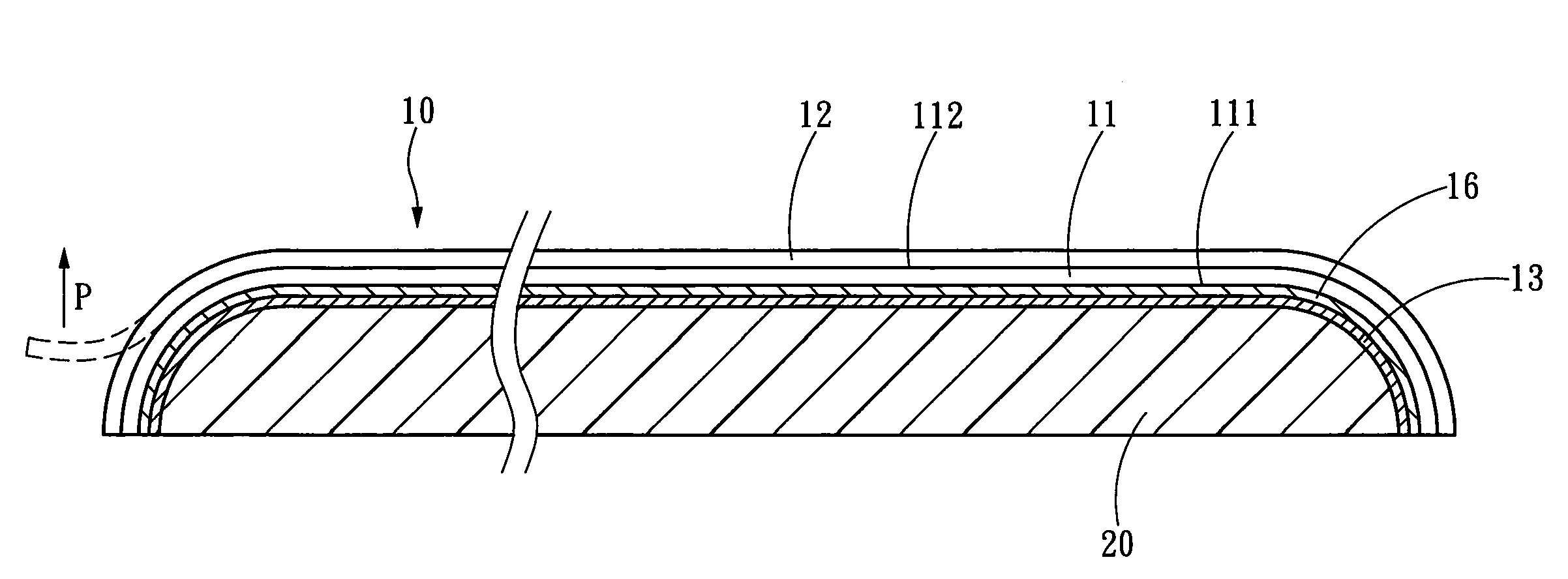
[0008]In yet another aspect, the hardened protection layer is exposed after the release base layer is released to isolate the patterns and texts from in contact with the exterior and provide abrasion resistance for the surface of the targeted object. Thus the invention can resolve the pollution and material waste problems occurred to the conventional thermal transfer printing that adopts spraying process and overcome the limitation of IMD technique of inapplicable to cubical products.

Problems solved by technology

Hence the thermal transfer printing quality and life span are easily affected.
However, spraying process not only creates environmental pollution also consumes a great amount of spraying material and results in a higher production cost.
While such a technique allows the decorative pattern to be covered by the hardened layer without directly exposed and damaged or scraped, applied to a cubical mold with a great curved angle chaps are prone to occur, and creases or air bubbles could be generated.
Hence its applicability is limited.

Method used


Image

  • Abrasion-resistant transfer printing structure
  • Abrasion-resistant transfer printing structure
  • Abrasion-resistant transfer printing structure

Examples


Embodiment Construction

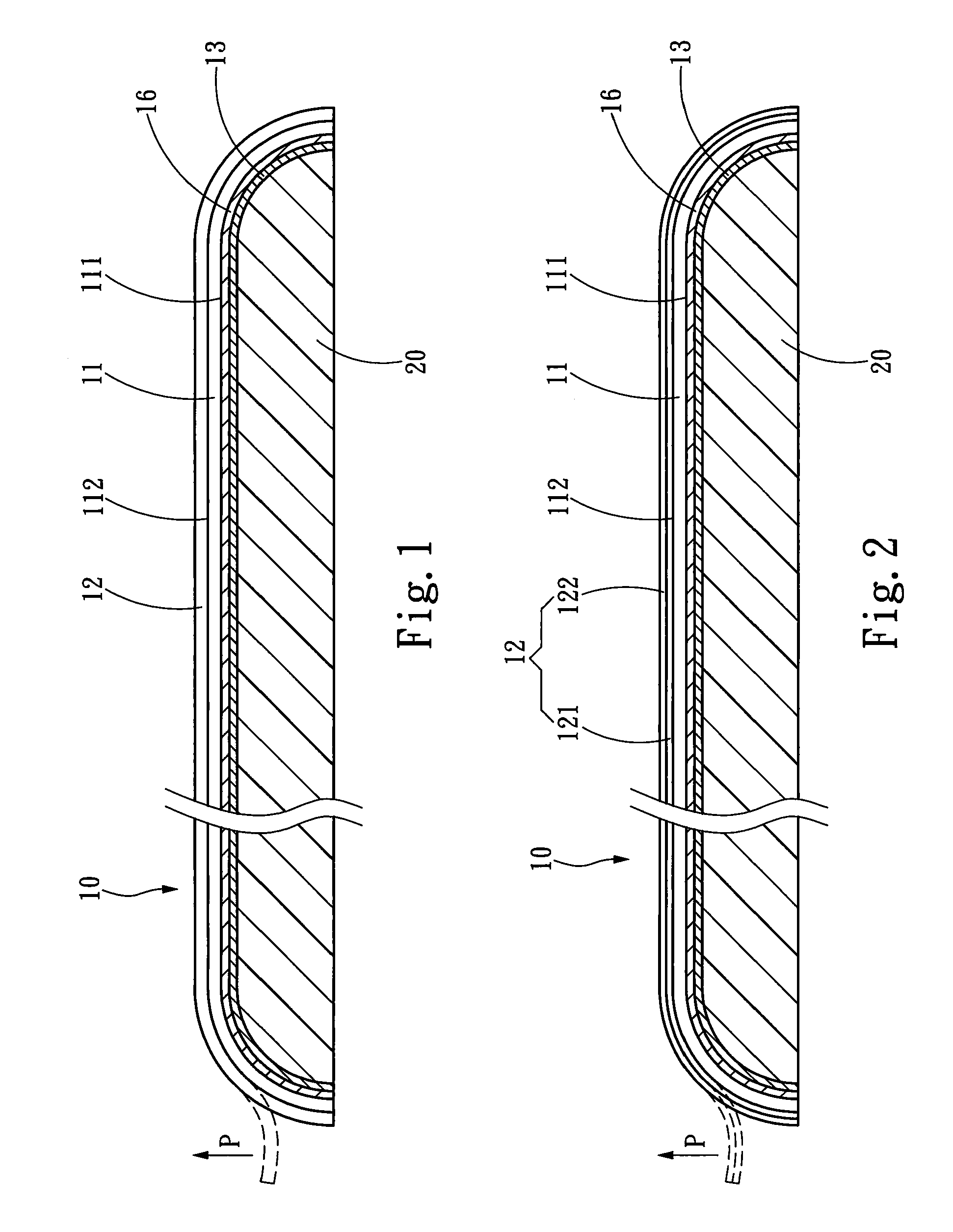
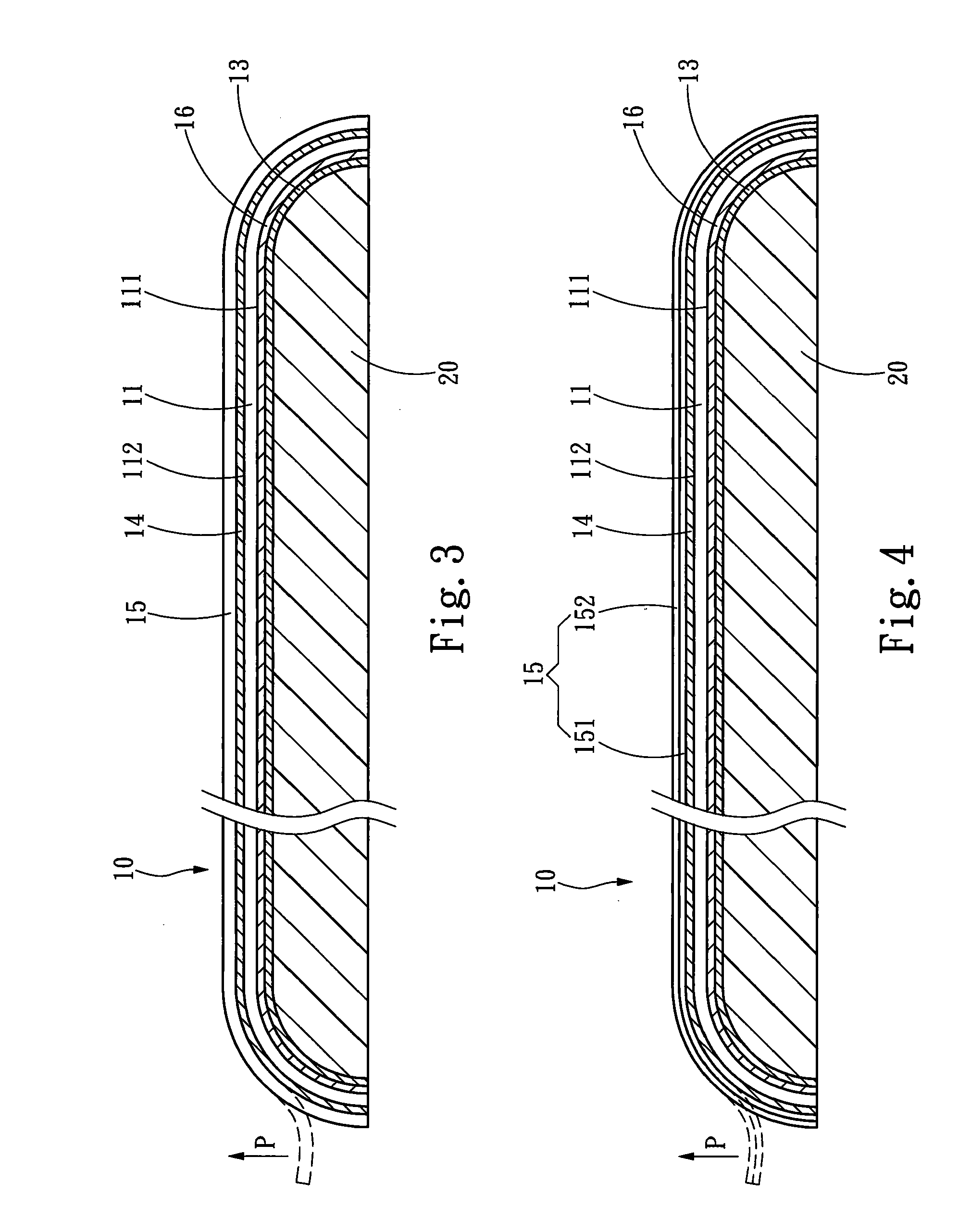
[0014]Please refer to FIG. 1 for an embodiment of the invention. The abrasion-resistant transfer printing structure 10 according to the invention aims to transfer patterns and texts to the surface of a targeted object 20 by press printing. The targeted object 20 may be made from a wide variety of materials, such as polycarbonate (PC), acrylonitrile-butadiene-styrene (ABS), polymethylmethacrylate (PMMA), polyoxymethylene (POM), polybutylene terephthalate (PBT) and the like. The targeted object 20 may have a flat surface, or a surface inclined at an angle between at least 10°˜90°. The transfer printing structure 10 includes at least a hardened protection layer 11 and a release base layer 12. The hardened protection layer 11 includes a first surface 111 and a second surface 112. The first surface 111 allows a transfer printing glue 13 to be bonded to the targeted object 20 to cover at least an area corresponding to the patterns and texts. The release base layer 12 is located on the sec...


PUM

PropertyMeasurementUnit
Temperatureaaaaaaaaaa
Thicknessaaaaaaaaaa

Abstract

An abrasion-resistant transfer printing structure to transfer patterns and texts to a targeted object surface by press printing includes a hardened protecting layer and a release base layer. The hardened protection layer includes a first surface and a second surface. The first surface allows a transfer printing glue to be bonded to the targeted object to cover at least an area corresponding to the patterns and texts. The release base layer is located on the second surface of the hardened protection layer by a releasable manner and can be separated from the hardened protection layer by applying a release force after the press printing process is finished. Thus the hardened protection layer is exposed to isolate the patterns and texts from in contact with the exterior. The surface of the targeted object also is abrasion resistant.

Description

FIELD OF THE INVENTION[0001]The present invention relates to a transfer printing structure and particularly to an abrasion-resistant transfer printing structure.BACKGROUND OF THE INVENTION[0002]Transfer printing technique aims to transfer patterns and texts on a carrier film to a targeted object by pressure to generate appearance diversity of the object. Advance of technology makes transfer printing technique widely adopted on the surface of many types of material, such as metal, glass, plastics, ceramics and the like.[0003]Among the transfer printing techniques, thermal transfer printing technique is most widely adopted. It adopts a principle by printing a pattern to be transferred on a heat-resistant base film, disposing the base film contained the pattern on the surface or location of a targeted object, and applying heat and pressure to transfer the pattern to the targeted object. In the conventional thermal transfer printing, the printing layer of the pattern is directly exposed...

Claims


Application Information

Patent Timeline
IPC IPC(8): B32B3/10C09J7/02C09J7/40
CPCB32B27/08B32B27/36C09J7/0225C09J2467/005Y10S428/913Y10S428/914Y10T428/14Y10T428/2848Y10T428/1471Y10T428/24843Y10T428/1486Y10T428/28Y10T428/24802B32B27/302B32B27/304B32B27/308B32B27/32B32B27/365B32B27/40B32B2255/205B32B2270/00B32B2274/00B32B2307/554B32B2307/702B32B2307/748C09J7/40
Inventor WANG, SHUN-CHENGHUANG, SHIH-MINCHEN, WEN-JUNGLIAO, CHIH-YUAN
Owner SIPIX CHEM
Learn More