
Thermokeratoplasty Systems

a technology of thermokeratoplasty and system, applied in the field of keratoplasty, can solve the problems of reshaping the central cornea, requiring a healing period, stress that tends to reshape the cornea,

Active Publication Date: 2010-06-24
TRUSTEES OF DARTMOUTH COLLEGE THE
View PDF62 Cites 0 Cited by
  • Summary
  • Abstract
  • Description
  • Claims
  • Application Information

AI Technical Summary

Benefits of technology

The system enhances predictability and safety of vision correction by ensuring precise thermal management and minimizing astigmatic effects and thermal damage, allowing for more effective and controlled reshaping of the cornea.

Problems solved by technology

Invasive surgical procedures, such as laser-assisted in-situ keratonomileusis (LASIK) may be used, but there are associated complications, such as the dry eye syndrome associated with severing of corneal nerves, and the need for a healing period after surgery.
Generally, the cornea is heated to a point where collagen fibers in the cornea shrink, which results in stresses that tend to reshape the cornea.
Application of energy in this manner may cause reshaping that flattens the central cornea when the energy is applied in circular or ring-shaped patterns around the pupil.
A number of problems have arisen in use of prior microwave applicator devices.
Chiefly, the amount of applied energy is unpredictably related in terms of a precise biological effect, such as by administering energy to produce a predetermined amount of vision correction.
There is no clear way to determine in the course of treatment if, for example, the outermost layer of corneal cells known as the epithelium is undergoing thermal damage as a result of treatment, and this uncertainty can lead to a painful period of healing while the epithelium regenerates.
Even small machining errors in these dimensions result in the applicator producing asymmetric treatment rings and associated astigmatic effects on the “corrected” vision resulting from use of these devices.

Method used


Image

  • Thermokeratoplasty Systems
  • Thermokeratoplasty Systems
  • Thermokeratoplasty Systems

Examples


Embodiment Construction

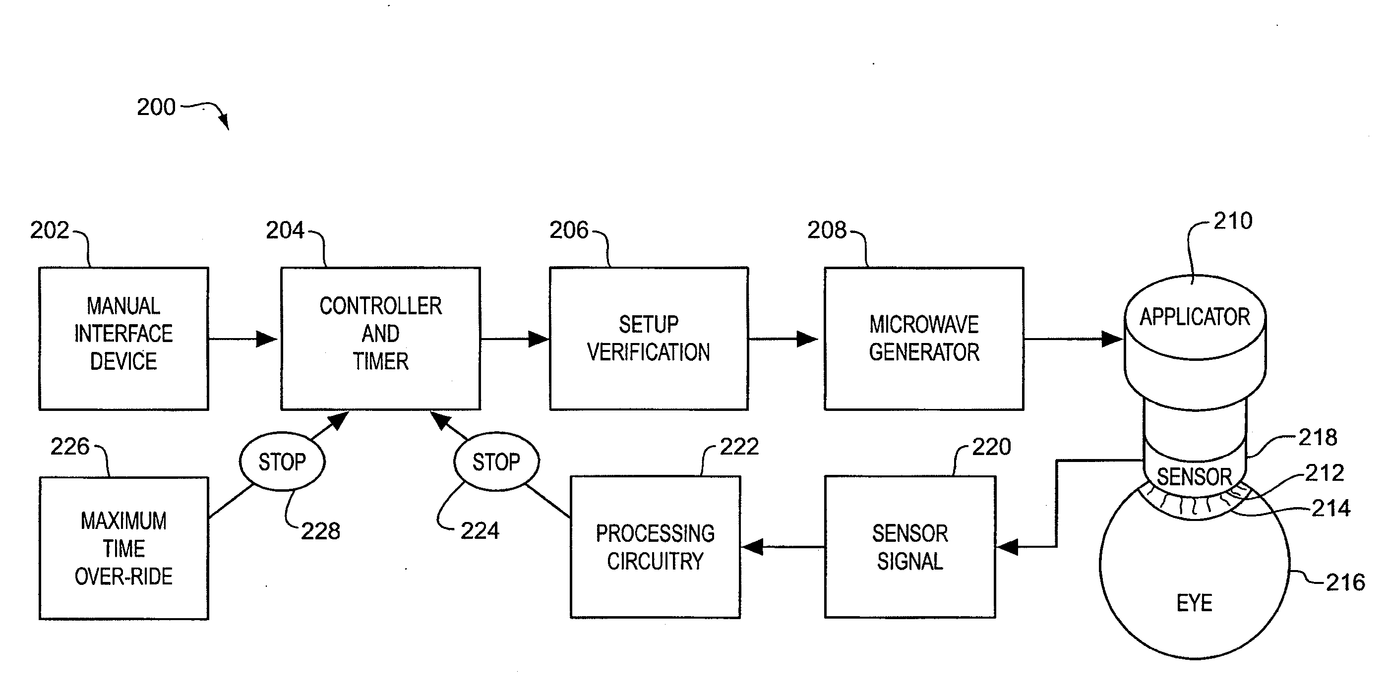
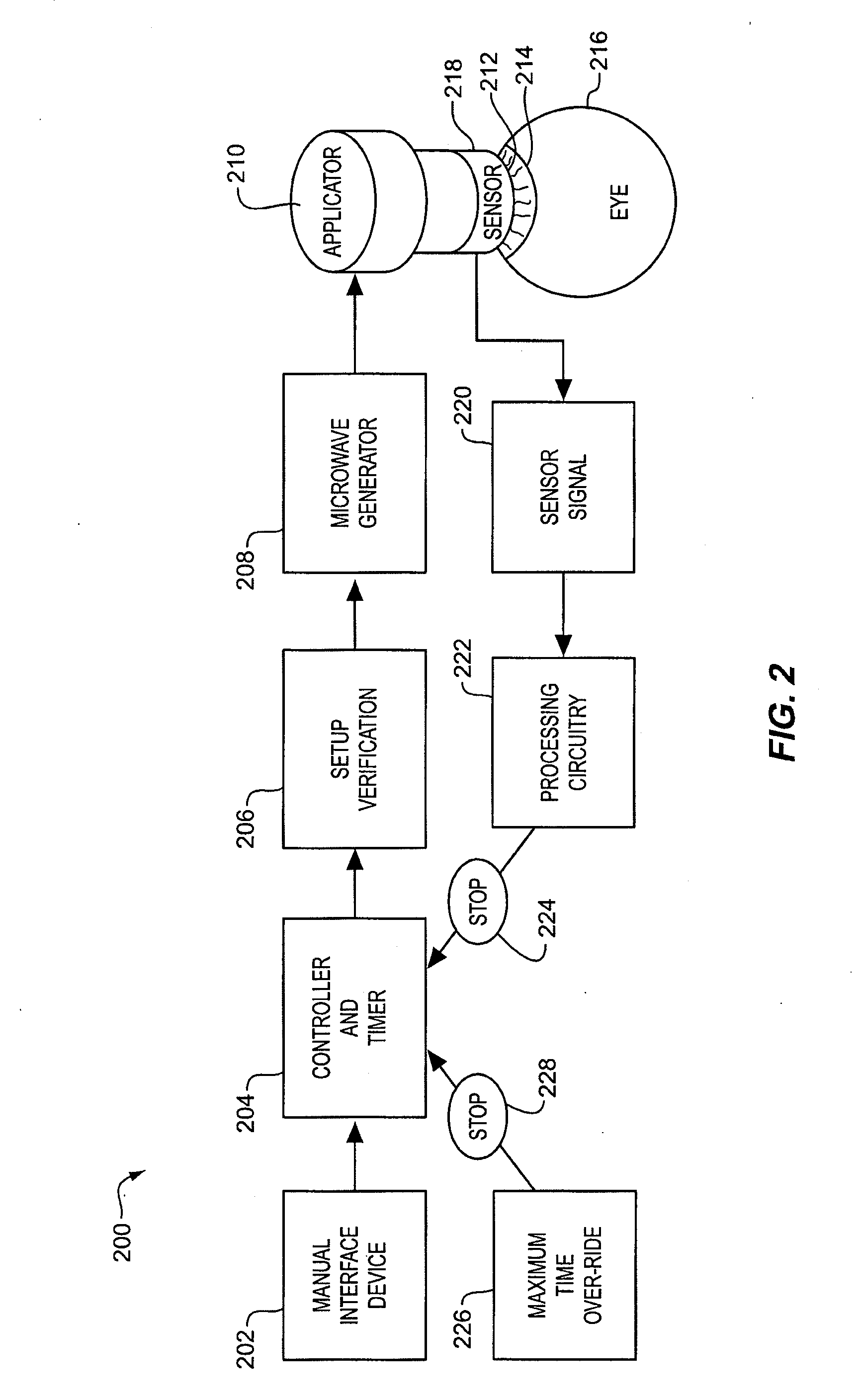
[0033]In FIG. 2, there will now be shown and described, by way of example and not by limitation, a thermokeratoplasty system 200 that operates by sensing a physical variable in an eye and providing sensed feedback affecting a vision correction modality. A physician or other medical worker manually accesses an interface device 202, such as a computer keyboard, that facilitates the selection and / or initiation of a treatment modality. The interface device 202 may request manual input, such as a predetermined amount of diopter correction that is required for a particular patient, baseline measurements of physical variables, astigmatism measurements, wavelength of microwave radiation, intensity of microwave radiation, selection of a treatment modality by specific selection or class of modality, and / or goals for adjusted physical variables obtainable as a result of treatment.

[0034]A programmable controller 204 accepts program instructions that optionally access user input data or program ...


PUM


Abstract

The present invention provides applicators for performing thermokeratoplasty. One embodiment of such applicators includes a pair of electrical conducting elements electrically separated by a selected distance and extending from a proximal end to a distal end. The electrical conducting elements define, at the distal end, a contact surface that is positionable at a cornea. At least one of the electrical conducting elements is divided into a plurality of discrete sections extending from the proximal end to the distal end. The discrete sections are selectively and separately actuated by a controller according to one or more variable characteristics to deliver energy to the cornea.

Description

REFERENCE TO RELATED APPLICATIONS[0001]This application is a continuation of U.S. patent application Ser. No. 11 / 688,146, filed Mar. 19, 2007, which is a continuation of U.S. patent application Ser. No. 10 / 730,327, filed Dec. 8, 2003, now U.S. Pat. No. 7,192,429, which was a continuation-in-part of U.S. patent application Ser. No. 10 / 314,670, filed Dec. 9, 2002, now U.S. Pat. No. 7,377,917, each of which is incorporated by reference herein.BACKGROUND[0002]The invention pertains to the field of keratoplasty and, more particularly, to thermokeratoplasty, especially electrically-induced thermokeratoplasty such as radio frequency or microwave thermokeratoplasty.[0003]The object of keratoplasty is to correct vision by reshaping of the cornea. For nearsighted persons, this reshaping involves flattening that ideally decreases the refractive power of the eye and causes the image to focus upon the retina, as opposed to focusing images in front of the retina. Invasive surgical procedures, suc...

Claims


Application Information

Patent Timeline
Patent Type & Authority Applications(United States)
IPC IPC(8): A61F9/013A61B18/14A61F9/007A61B17/00A61B18/00A61B18/18
CPCA61B18/18A61B18/1815A61B2017/00084A61F9/013A61F9/007A61F9/0079A61B2018/00023
Inventor TREMBLY, B. STUART
Owner TRUSTEES OF DARTMOUTH COLLEGE THE
Learn More