Thermal treatment device

Inactive Publication Date: 2010-06-24
JOHNSON & JOHNSON CONSUMER COPANIES
View PDF65 Cites 45 Cited by
  • Summary
  • Abstract
  • Description
  • Claims
  • Application Information

AI Technical Summary

Problems solved by technology

These types of products have the disadvantage of having loose powder formulations that do not always adequately conform to parts of the skin and do not conduct heat thoroughly to the skin since a woven or non-woven fabric surface is in contact with the skin.
Such a device involves excess bulk, is non-discreet and requires the use of exter

Method used


Image

  • Thermal treatment device
  • Thermal treatment device
  • Thermal treatment device

Examples


Embodiment Construction

[0025]As used herein, unless otherwise indicated, the term substantially is understood to mean at least about 60%. More preferably, at least about 75%.

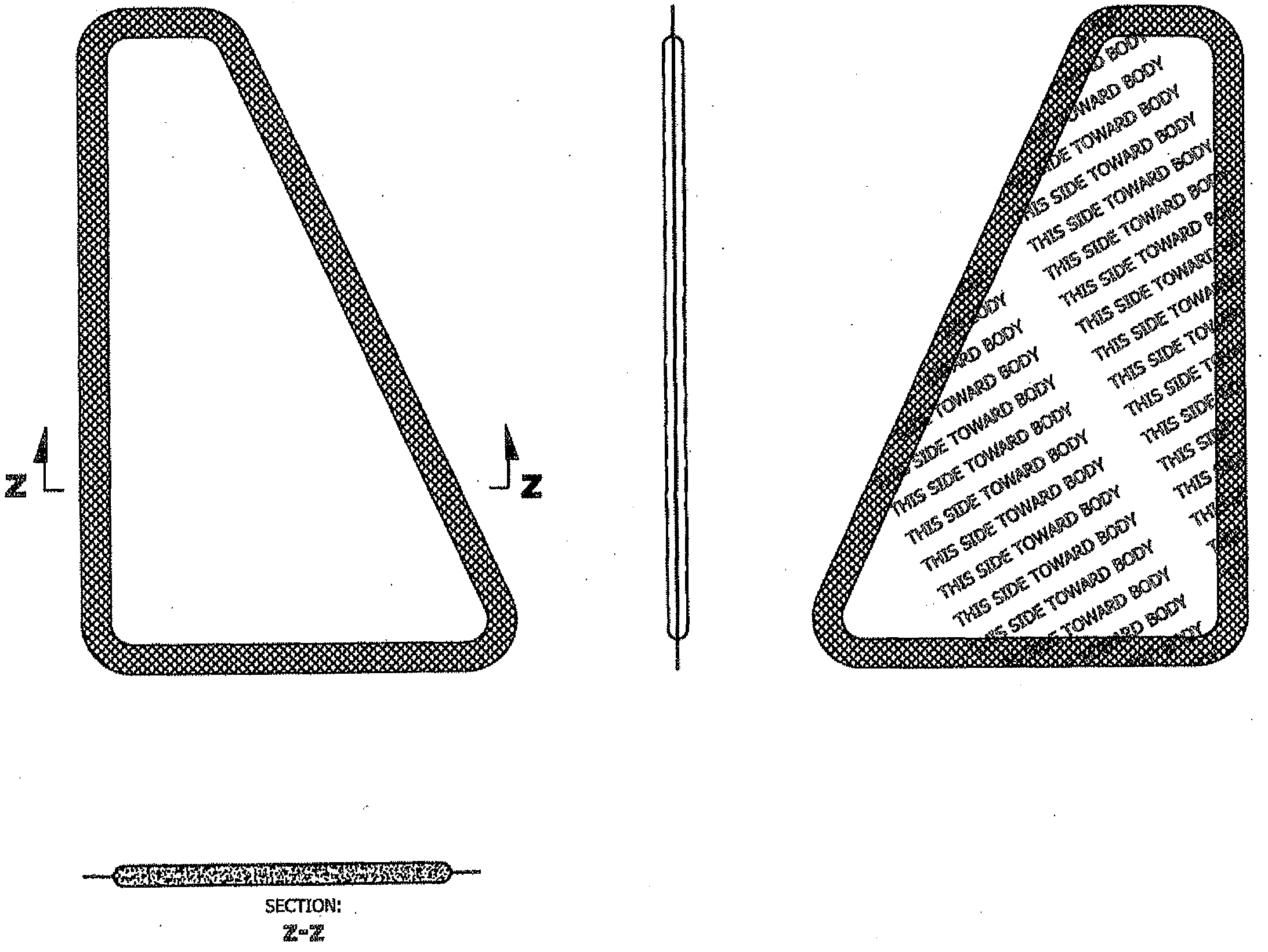
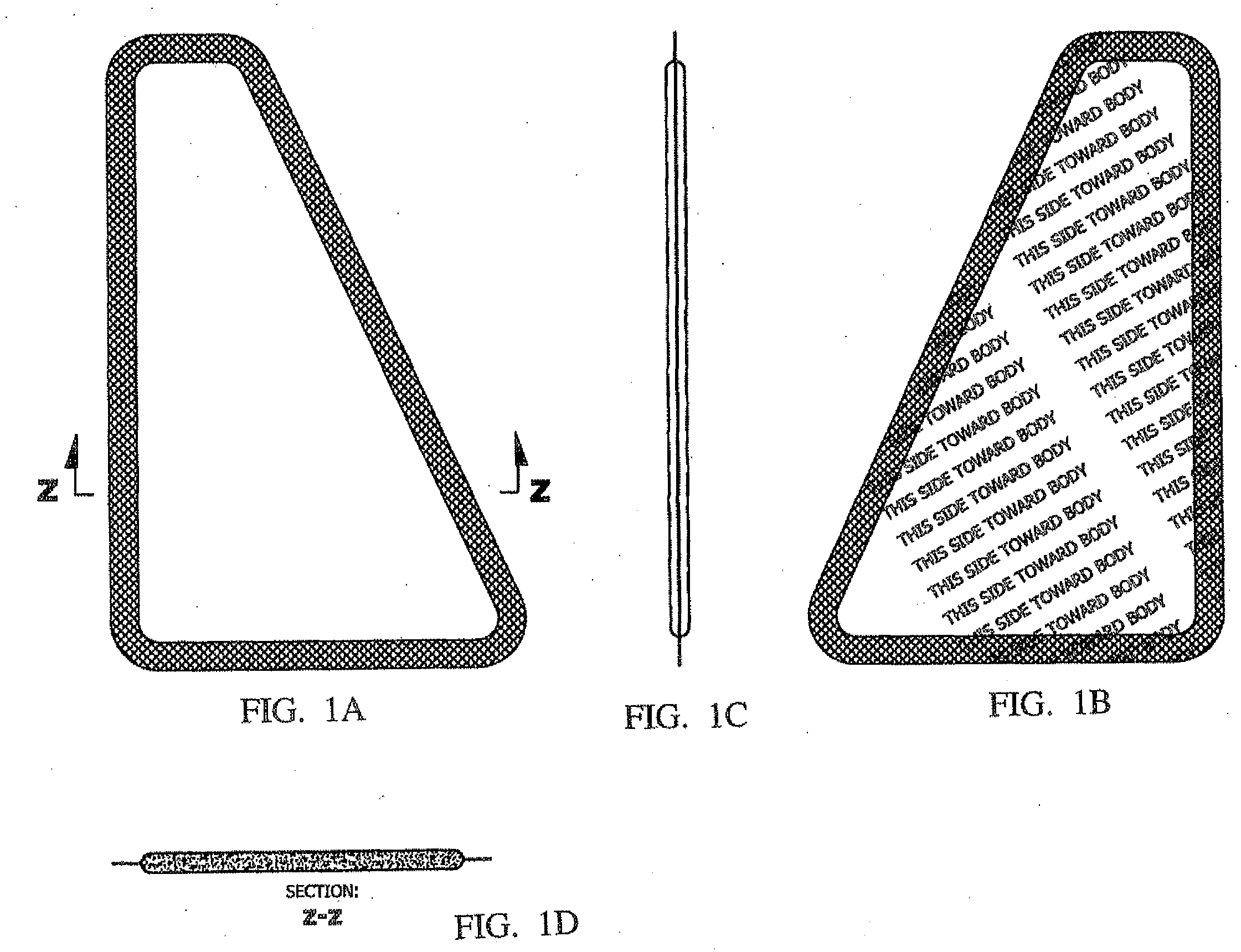
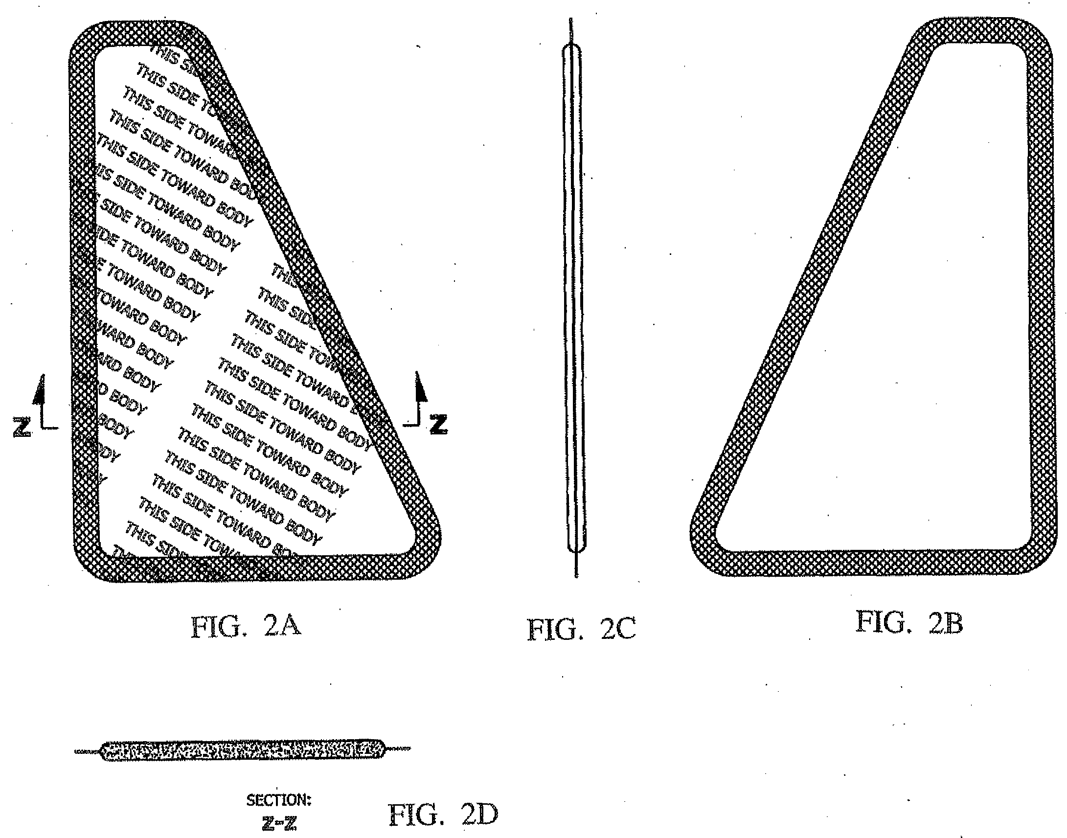
[0026]The present invention relates to a thermal treatment device, e.g., thermal pad, for managing muscle and joint pain that is worn in close proximity to the skin of a human. The thermal treatment device offers the benefit of improved therapeutic relief by substantially covering the surface of the affected muscle groups, thereby targeting treatment of those particular muscle groups. By designing the thermal treatment device with the particular shape of a muscle or muscle group, the device can be used for either treating the back, neck or shoulder of the human body. The particular shape and dimensions of the device of the present invention have the added benefit of minimizing waste and manufacturing costs. The thermal treatment device, which may be substantially shaped as a trapezoid, may be designed for use on the right hand side of...


PUM


Abstract

A thermal treatment device to be worn in close proximity to the skin of a human is disclosed. The thermal treatment device comprises a thermal composition; wherein the device substantially covers the left or right trapezius muscle of the neck and shoulder or the left or right paraspinal muscles in the lower back and the tender point of the respective sacroiliac joint.

Description

BACKGROUND OF THE INVENTION[0001]1. Field of the Invention[0002]The present invention is directed to a thermal treatment device. More particularly, the present invention relates to a thermal treatment device that is contoured to cover the surface of the trapezius muscle or paraspinal muscles of the lower back.[0003]2. Related Background Art[0004]For patients with aching muscles and sore joints, the application of heat can decrease the viscosity of fluids, loosen stiff muscles, improve blood flow to the affected area, facilitate tissue repair, and create a feeling of relaxation. The application of heat to the skin as a means to penetrate deeper into tissues has historically been used for pain relief of muscles and joints, as well as for the treatment of certain inflammatory conditions. For some acute injuries, the application of cold can numb pain, constrict blood vessels and mitigate the inflammatory response. The application of cold materials to the skin has also been used for simi...

Claims


Application Information

Patent Timeline
IPC IPC(8): A61F7/08
CPCA61F7/02A61F7/03A61F2007/0011A61F2007/0246A61F2007/0027A61F2007/0203A61F2007/0226A61F2007/0025
Inventor LYNCH, JOSEPH M.SOWDEN, HARRY S.ROBINSON, RONNI L.WIET, STEPHAN G.KRIKSUNOV, LEO B.
Owner JOHNSON & JOHNSON CONSUMER COPANIES
Why Eureka
Try Eureka