Intraocular lens insertion device and method for controlling movement of the intraocular lens

a technology of intraocular lens and insertion device, which is applied in the field of intraocular lens insertion device and, can solve the problems of damage or breakage of the optic or the trailing supporting portion, take time and labor in surgery, etc., and achieve the effect of simple configuration and more reliable control of the supporting portion

Active Publication Date: 2010-06-24
HOYA CORP
View PDF100 Cites 94 Cited by
  • Summary
  • Abstract
  • Description
  • Claims
  • Application Information

AI Technical Summary

Benefits of technology

[0023]According to the intraocular lens insertion device set forth in claim 1 of the present invention, the pushing portion provided on the plunger moves an intraocular lens forward with the supporting portion being caught, thereby preventing the supporting portion from stretching backward as the intraocular lens is moving forward. Therefore, with this intraocular lens insertion device, the supporting portions can be inserted together with the optic into an eye through an incision at one operation, thereby omitting a repeated operation after the intraocular lens was inserted into the eye.
[0024]According to the intraocular lens insertion device set forth in claim 2 of the present invention, the optic and the supporting portion arranged in the backward direction of the lens advancing axis are prevented from being damaged or broken while the intraocular lens is moving.
[0025]According to the intraocular lens insertion device set forth in claim 3 of the present invention, the intraocular lens is moved forward with a minimum of interference of the optic and the supportin

Problems solved by technology

With such an intraocular lens insertion device, however, there was a problem that a supporting portion arranged in the backward direction of a lens advancing axis (hereinafter, referred to as a trailing supporting portion) got caught in the gap between a plunger for pushing out the intraocular lens and an inner wall of a passage of the insertion device or entangled in the plunger in a process of movement of the intraocular lens.
Such a problem is brought to the fore especially with a soft intraocular lens having thin filament-

Method used


Image

  • Intraocular lens insertion device and method for controlling movement of the intraocular lens
  • Intraocular lens insertion device and method for controlling movement of the intraocular lens
  • Intraocular lens insertion device and method for controlling movement of the intraocular lens

Examples


embodiment

1. Embodiment

(1) General Structure

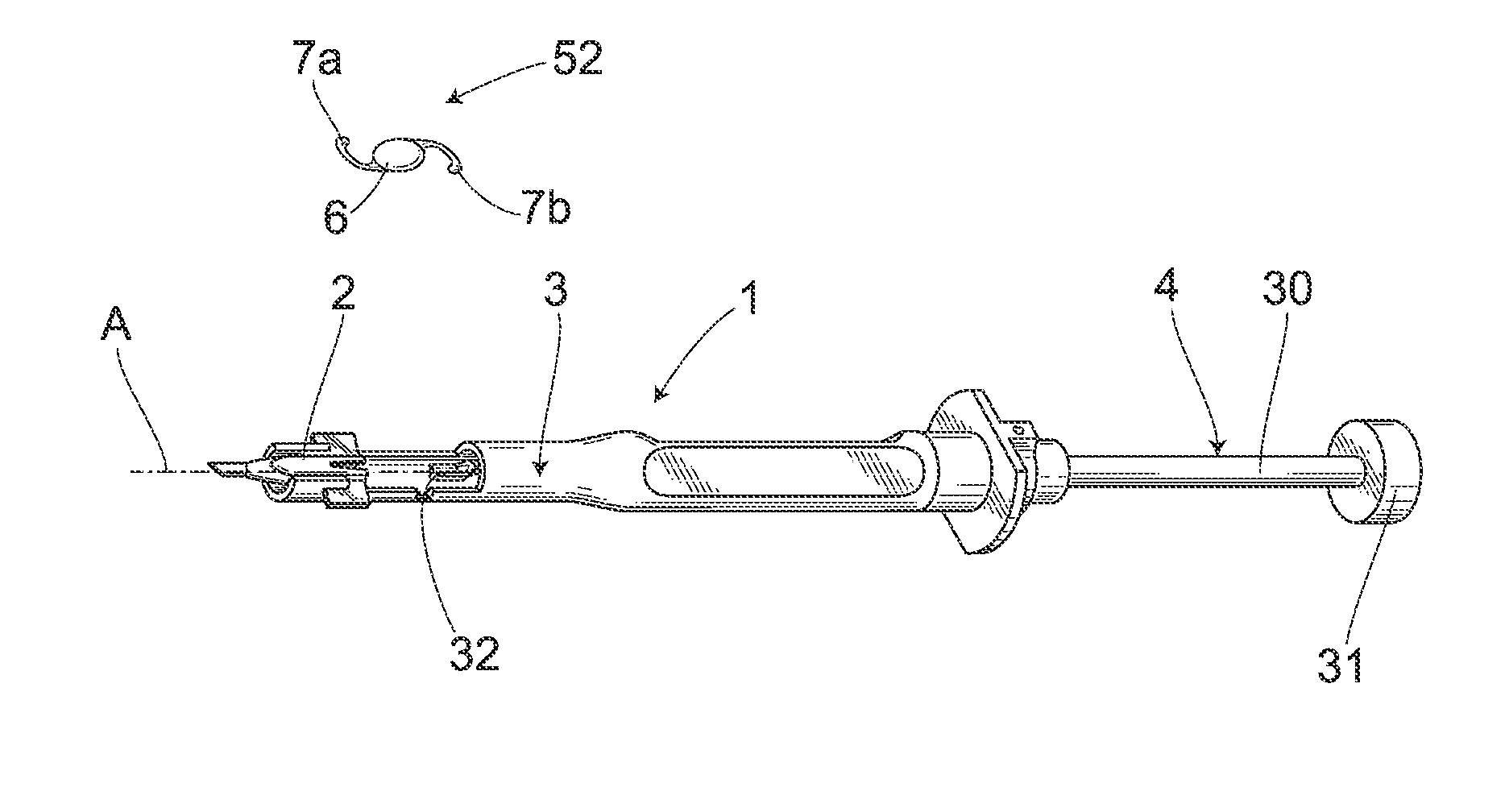
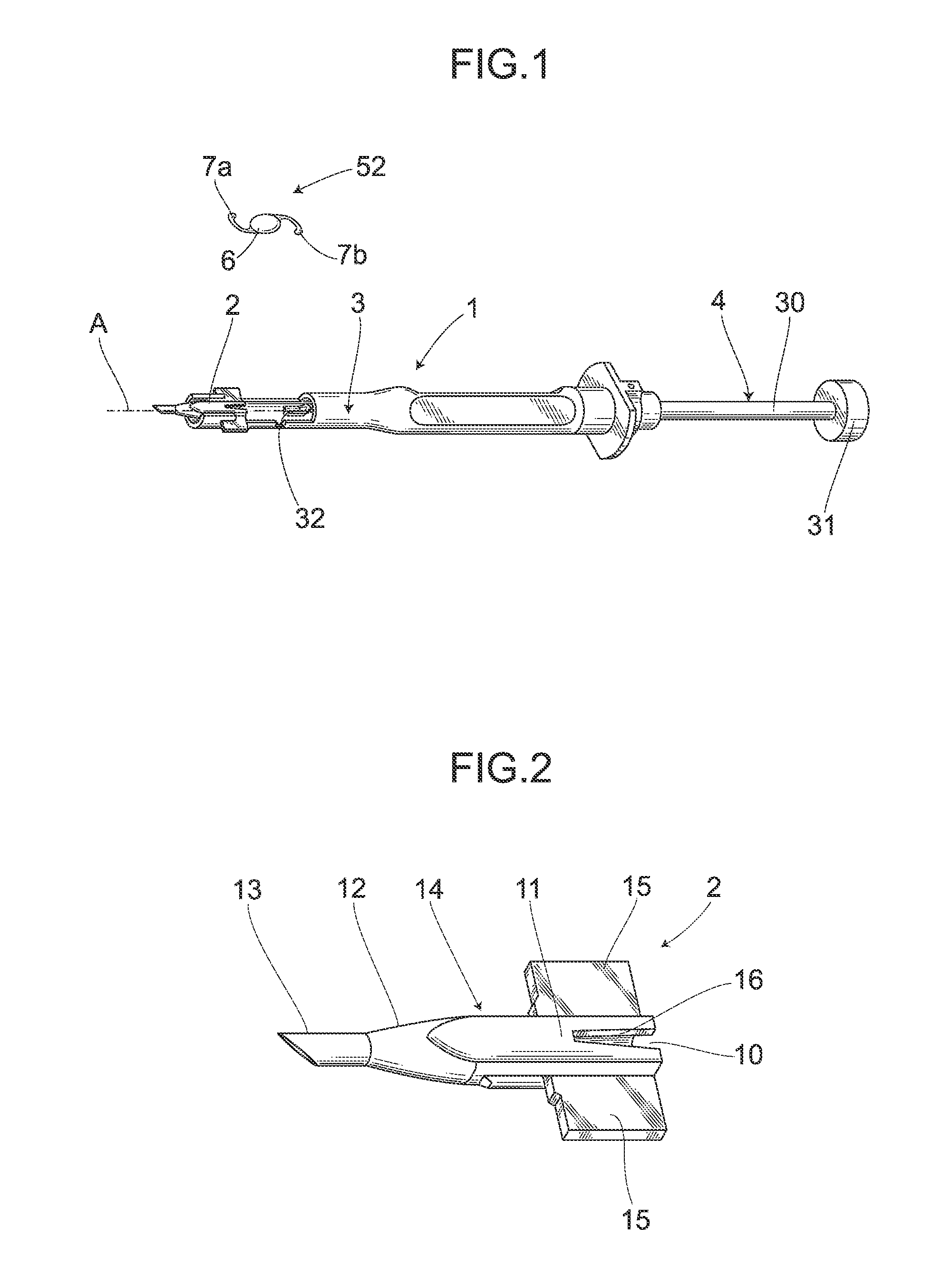
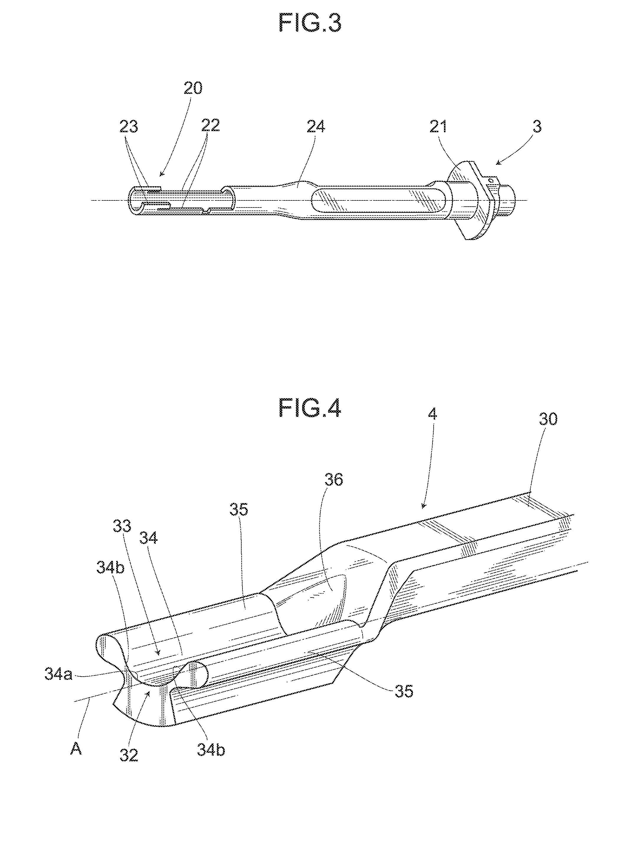
[0041]An intraocular lens insertion device 1 shown in FIG. 1 has a cartridge 2, a main body 3 and a plunger 4. The cartridge 2 is installed to the main body 3 after an intraocular lens 5 is set on the cartridge. On the other hand, the plunger 4 is provided so that it can move in the forward and backward directions of the lens advancing axis A inside the main body 3. The intraocular lens insertion device 1 having such a configuration is generally configured to push out the intraocular lens 5 set in the cartridge 2 by using the plunger 4 and to release the intraocular lens 5 from the end of the cartridge 2 into an eye.

[0042]For reference's sake, an intraocular lens insertion device 1 may be made of various materials. For example, synthetic resin may be used for all portions of the tool, thereby allowing easy mass production; or metal such as titanium may be used. The intraocular lens 5 also has an optic 6 and a pair of thin plate-like supporting porti...


PUM


Abstract

Provided is an intraocular lens insertion device capable of omitting a repeated operation after the intraocular lens is inserted into the eye. The intraocular lens insertion device (1) comprises a lens setting part (11) for mounting an intraocular lens (5) having an optic (6) and one or two or more supporting portions (7a and 7b) disposed at the outer edge of the optic (6), a plunger (4) for pushing out the intraocular lens (5) mounted in the lens setting part (11), and a nozzle (13) for releasing the intraocular lens (5) pushed out by the plunger (4). This plunger (4) includes a lens contact portion (32) for abutting against the outer edge of the optic (6), and a pushing portion (33) for pushing out the supporting portion (7b) arranged in the backward direction of a lens advancing axis (A).

Description

TECHNICAL FIELD[0001]The present invention relates to an intraocular lens insertion device and a method for controlling movement of the intraocular lens used to implant an intraocular lens into an eye in place of a crystalline lens removed in cataract surgery.BACKGROUND ART[0002]In cataract surgery, there has been widely performed removal of opacified crystalline lenses by phacoemulsification and aspiration (PEA) followed by implantation of intraocular lenses into aphakic eyes. There are two types of intraocular lens: a hard intraocular lens whose optic is made of a hard material such as PMMA and a soft intraocular lens whose optic is made of a flexible material such as silicone elastomer, soft acrylic or hydrogel.[0003]Upon use of a hard intraocular lens, the lens needs to be inserted through an incision having been cut in a cornea or sclera in a width approximately the same as the diameter of the optic of the lens. On the other hand, upon use of a soft intraocular lens, the lens c...

Claims


Application Information

Patent Timeline
IPC IPC(8): A61F2/16A61B17/00
CPCA61F2/167
Inventor INOUE, MASANOBU
Owner HOYA CORP
Why Eureka
Try Eureka