Method for identification of traffic lane boundary

Active Publication Date: 2010-06-24
NATIONAL CHIAO TUNG UNIVERSITY
View PDF7 Cites 8 Cited by
  • Summary
  • Abstract
  • Description
  • Claims
  • Application Information

AI Technical Summary

Benefits of technology

[0011]The invention can reduce the wrong judgment in unknown lane area under the situation of a given frequency span information.
[0012]The invention can use a faster and more accurate calculation way to identi

Problems solved by technology

It is a real difficult job.
The main reason is that when the vehicles pass through different lanes, it is unable to distinguish lane boundary accurately to obtain the vehicle information on every lane, due to the reflection of microwave generated by near the adjacent lanes.
Due to the traffic lane being fixed, there is no more flexible calculation for lane width, so that it is still d

Method used


Image

  • Method for identification of traffic lane boundary
  • Method for identification of traffic lane boundary
  • Method for identification of traffic lane boundary

Examples


Example

[0023]The invention provides the frequency span information and the probability density model to form an automatic learning mechanism, in order to identify the correct lane boundary position.

[0024]The invention provides a method for identification of traffic lane boundary, which is described in detail as follows:

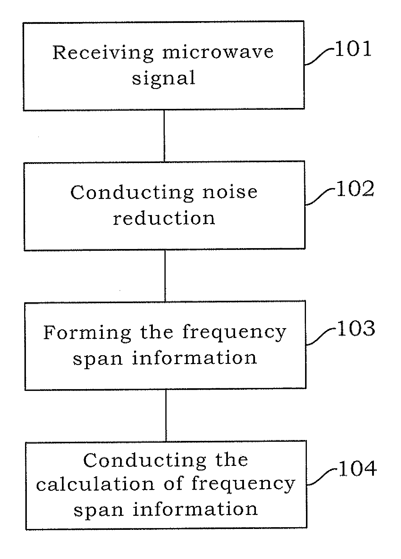
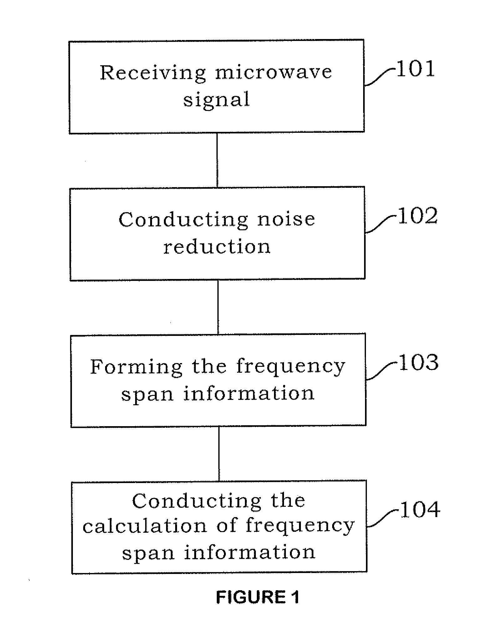
[0025]FIG. 1 shows the flow chart of a preferred embodiment. As shown in Step 101, the microwave signal is received firstly, and then the voltage signal is converted to frequency domain information by Fourier Transformation.

[0026]As shown in Step 102 of FIG. 1, the noise reduction is treated for the frequency domain information. Thus, the unnecessary frequency domain information from the microwave signal is filtered.

[0027]As shown in Step 103 of FIG. 1, the frequency domain information is employed to calculate the legal set of closed interval, in order to form the frequency span information.

[0028]Finally, as shown in Step 104 of FIG. 1, the probability density model is emplo...


PUM


Abstract

The invention provides a method for identification of traffic lane boundary. Firstly the microwave signal is received, and the noise reduction is treated for the microwave signal. Then the frequency domain information is employed to calculate the legal set of closed interval, in order to form the frequency span information. Finally, the probability density function model is employed to calculate the frequency span information in order to identify the traffic lane boundary.

Description

BACKGROUND OF THE INVENTION[0001]1. Field of the Invention[0002]The invention provides a method for identification of traffic lane boundary, particularly a method for identification of traffic lane boundary by applying the frequency span information and the probability density function model.[0003]2. Description of the Prior Art[0004]When the radar microwave detector is used to count the number of vehicles of every lane in multiple lanes at the same time, it has to set up the information of lane boundary first. It is a real difficult job. The main reason is that when the vehicles pass through different lanes, it is unable to distinguish lane boundary accurately to obtain the vehicle information on every lane, due to the reflection of microwave generated by near the adjacent lanes.[0005]As the provided prior art for the other radar microwave technology application to the identification of traffic lane, in US Patent No. US2007 / 0016359A1 “Method and Apparatus for Providing Automatic La...

Claims


Application Information

Patent Timeline
IPC IPC(8): G08G1/00
CPCG08G1/015G01S13/91G01S13/931G08G1/048
Inventor JOU, YOW-JENCHO, HSUN-JUNGCHEN, YU-KUANGHUANG, HENGHSU, CHIA-CHUNLI, RIH-JINLAN, CHIEN-LUNTSENG, MING-TE
Owner NATIONAL CHIAO TUNG UNIVERSITY
Why Eureka
Try Eureka