
Device and method for mounting a needle guard on a syringe body

Inactive Publication Date: 2010-07-01
ROBERT BOSCH GMBH
View PDF31 Cites 91 Cited by
  • Summary
  • Abstract
  • Description
  • Claims
  • Application Information

AI Technical Summary

Benefits of technology

[0006]Preferably, the device further includes a holding-down device, which is disposed above the retainer of the syringe body. The holding-down device can be put into contact with the other end of the syringe body and furnishes a counterforce to the placement force for placement of the needle guard on the syringe body.
[0008]Also preferably, the device of the invention includes a force sensor, for picking up a force of the placement of the needle guard on the syringe body. The use of the force sensor makes it possible to determine, from the placement force, whether the needle guard has been placed correctly and securely on the syringe body. As a result, as soon as the needle guard is put in place, syringes that have a needle guard placed with too great or too little placement force can be rejected.
[0009]The first sensor is preferably disposed on the holding-down device. As a result, an especially compact construction can be assured.
[0010]The device according to the invention further preferably includes a control device with a memory, and in the memory, at least one predetermined force value for the placement force is stored. The control device serves to compare a picked-up placement force with the predetermined placement force and if needed to reject the syringe if the placement force is wrong. It should be noted that both a lower limit for the placement force and an upper limit for the placement force can be monitored here.
[0011]Especially preferably, the first displacement device and the second displacement device are activated simultaneously. As a result, an especially short time for placing the needle guard on the syringe body can be assured. [in other words, it can be assured that it is especially fast]

Problems solved by technology

In particular upon closure of a syringe provided with a needle and a needle guard, however, a situation can often occur in the prior art in which the needle guard is put in place skewed, so that the needle of the syringe touches the needle guard and might become bent, or that the needle pierces the needle guard.

Method used


Image

  • Device and method for mounting a needle guard on a syringe body
  • Device and method for mounting a needle guard on a syringe body
  • Device and method for mounting a needle guard on a syringe body

Examples


Embodiment Construction

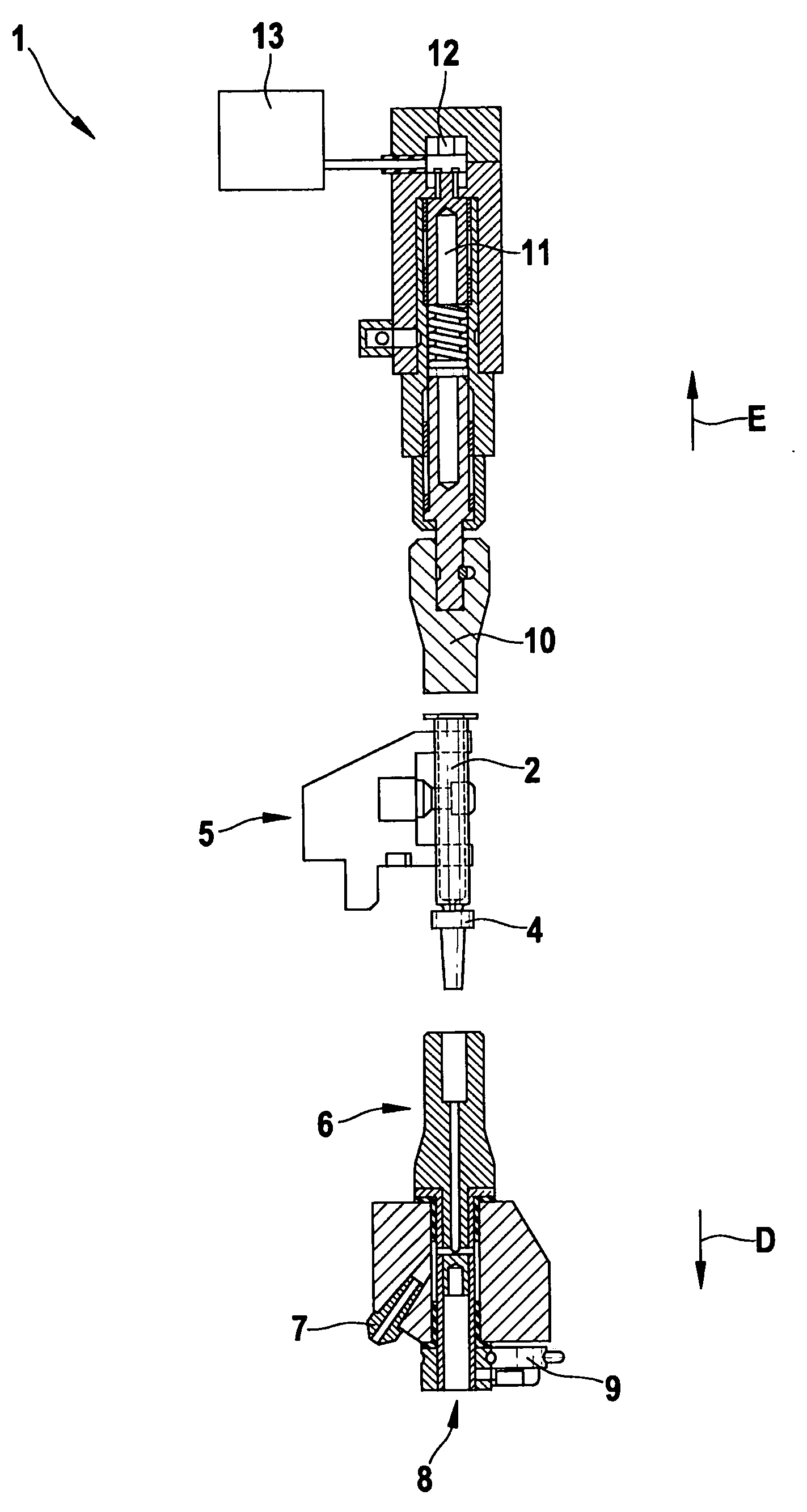
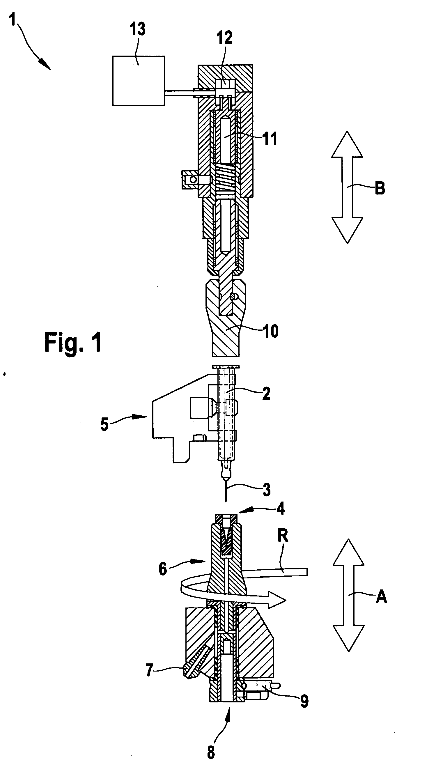
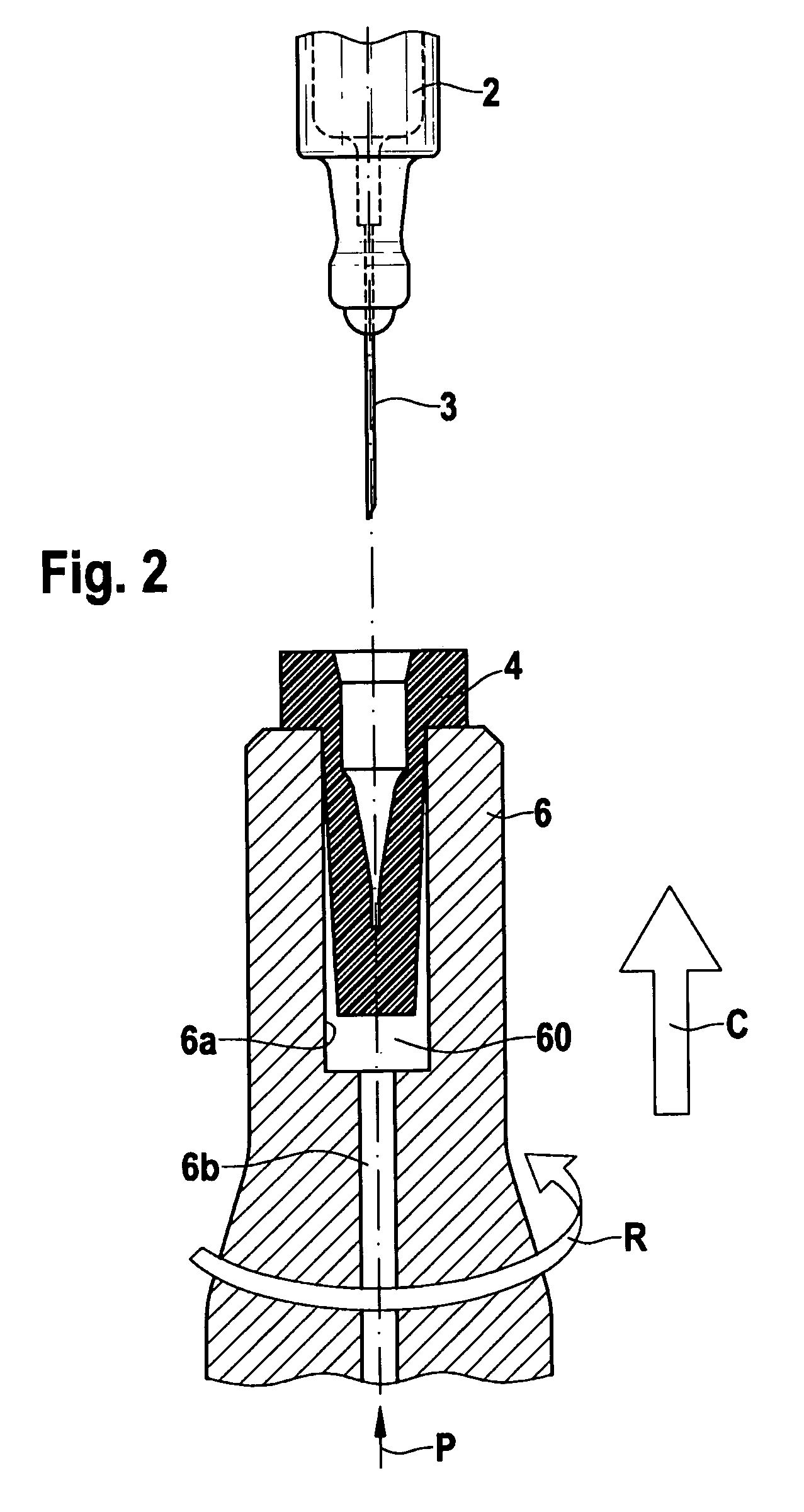
[0019]Below, in conjunction with FIGS. 1 through 4, a device 1 for mounting a needle guard 4 on a syringe body 2 will be described in detail.

[0020]FIG. 1 schematically shows the overall construction of the device 1. The device 1 includes a retainer 5 for retaining the syringe body 2. The retainer 5 may for instance be a gripping unit or the like. The device 1 furthermore includes a needle guard receptacle 6 and a holding-down device 10. As indicated by the double arrow A in FIG. 1, the needle guard receptacle 6 can be moved up and down in the vertical direction in the direction of the retainer 5. Moreover, the needle guard receptacle can be rotated in the direction of the arrow R. The entire needle guard receptacle 6 is rotated and moved in the vertical direction. The rotation is done over a predetermined angle, such as 90°. The needle guard receptacle 6 is moved in the vertical direction by means of a first displacement device 8. The first displacement device 8 is for instance a pr...


PUM

PropertyMeasurementUnit
Forceaaaaaaaaaa
Displacementaaaaaaaaaa

Abstract

The invention relates to a device for mounting a needle guard (4) onto a syringe body (2) that is provided with a needle (3), comprising a retaining device (5) for retaining the syringe body (2), a needle guard receptacle (6) for receiving the needle guard (4), a compressed air system (7) for providing compressed air, a first displacement device (8) for displacing the needle guard receptacle (6) in a vertical direction (A), and a rotation device (9) for at least partially rotating the needle guard receptacle (6), wherein the needle guard receptacle (6) is disposed beneath the retaining device (5), the compressed air being fed to the needle guard receptacle (6) such that the needle guard (4) is suspended on an air cushion (60) in a floating manner, and wherein the needle guard receptacle (6) can be displaced in a vertical direction (A) by means of the first displacement device (8). The invention further relates to a method for mounting the needle guard (4) onto the syringe body (2).

Description

PRIOR ART[0001]The present invention relates to a device for mounting a needle guard on a syringe body and to a method for mounting a needle guard on a syringe.[0002]From the prior art, various devices are known for delivering closures, especially for pharmaceutical containers. Such devices for instance include a vibration-promoting cup, which orients the closures and dispenses them into a feeder groove. The closures are delivered to a closing wheel, which takes the individual closures from the feeder groove and upon its further rotation sets them on bottles and then closes them.[0003]One such device is known for instance from German Patent Disclosure DE 103 22 476 A1. In it, a sorting device and the feeder groove are coupled to one another and movable jointly as a unit. In particular upon closure of a syringe provided with a needle and a needle guard, however, a situation can often occur in the prior art in which the needle guard is put in place skewed, so that the needle of the sy...

Claims


Application Information

Patent Timeline
IPC IPC(8): B23P21/00B23P19/04B25B27/14B23Q17/00B23P11/00
CPCA61M5/3202A61M2207/00B65B7/28Y10T29/53687Y10T29/53339Y10T29/49776Y10T29/49826Y10T29/53039Y10T29/49881Y10T29/53978
Inventor LEIDIG, JUERGEN
Owner ROBERT BOSCH GMBH
Learn More