System and method of wetting adiabatic material

a technology of adiabatic material and wetting process, which is applied in the field of system and method of wetting adiabatic material, can solve the problems of wasting a large amount of water during the dumping process, requiring a relatively long start-up period, and a relatively long period of time to fill the trough, so as to reduce the amount of wasted water, reduce the time required to saturate the moisture absorbent material from a dry condition, and reduce the amount of wasted

Inactive Publication Date: 2010-07-01
BALTIMORE AIRCOIL CO INC
View PDF35 Cites 23 Cited by
  • Summary
  • Abstract
  • Description
  • Claims
  • Application Information

AI Technical Summary

Benefits of technology

[0028]Embodiments of the invention that incorporate intermediate and temporary run-off water collection arrangements with any collected run-off water being directed to a sump for subsequent transfer by pump to a water distribution arrangement disposed above the adiabatic material may substantially reduce the amount of wasted water particularly where the dimensions of the sump and trough are substantially reduced as compared with existing trough arrangements. In particular, by using a trough as an intermediate run-off water collection arrangement below the adiabatic material and subsequently transferring run-off water to a sump, the sump may be dimensioned significantly smaller than standard trough arrangements whilst still maintaining the necessary head of pressure at the pump intake. In a prototype arrangement, it is expected that the sump size can be reduced from the usual 250 to 300 litres of water collection and storage that occurs in existing trough arrangements to as little as 40 litres.
[0029]Of course, where it is possible to operate a water recirculation system with a smaller sized sump, then the amount of wasted water is commensurately reduced as the regular dumping cycle will only result in the dumping of a smaller quantity of water.
[0030]In an embodiment of the invention that directs make-up water to a point in the water recirculation system subsequent to the outlet of the pump and prior to the inlet of the water distribution arrangement, the amount of time required to saturate the moisture absorbent material from a dry condition is reduced as compared with an arrangement where the make-up water is directed into a sump or trough in the first instance and subsequently pumped to the water distribution arrangement. Where make-up water is directed to a point between the outlet of the pump and the inlet of the water distribution arrangement, the time required to transition a cooling apparatus from dry mode to wet mode is substantially reduced as compared with existing systems. Where this delay is sufficiently reduced, the requirement to pre-emptively commence operation of the water recirculation system in anticipation of worsening climatic conditions is obviated. A more responsive water recirculation system that can transfer from dry to wet mode as quickly as possible has the associated benefit of avoiding more instances of false priming of the air cooling system and hence avoids the wastage of water in those instances where a false priming would otherwise occur.

Problems solved by technology

However, the water recirculation system looses water through vapourisation as it cools the air forced through the adiabatic material.
Of course, in the circumstances where a trough is relatively long, and hence contains a relatively large amount of water, then a relatively large amount of water is wasted during the dumping process.
A further disadvantage of the existing, and well accepted, water recirculation arrangement is the relatively long start-up period that is required to fully saturate the adiabatic material from a dry condition.
For example, many industrial cooling arrangements do not activate the water recirculation system until such time as the ambient air is sufficiently warm and thus requires cooling.
In arrangements where the trough has relatively large dimensions, it can take a relatively long period of time to fill the trough with water to a sufficient level to provide the necessary head of pressure at the pump intake.
Again, where the trough dimensions are relatively large, it may take some time for the trough to fill to a sufficient depth to safely activate the pump to commence the water recirculation process.
Clearly, the delay in filling the trough is affected by both the dimensions of the trough and the available water pressure to the float valve arrangement.
Of course, in those circumstances where the prediction of an increased heat exchange requirement is incorrect, the water recirculation process may be falsely commenced which saturates the adiabatic material and fills troughs with water for no reason.
However, such an increase in ambient air temperature may be followed by a substantial and potentially unexpected decrease in ambient air temperature thus not actually requiring a transition of the cooling arrangement from dry to wet mode.
Unfortunately, having filled the trough unnecessarily, once the regular lime period expires, the trough contents would be dumped in accordance with the trough water replacement schedule.
In these circumstances, the trough water is unnecessarily wasted.

Method used


Image

  • System and method of wetting adiabatic material
  • System and method of wetting adiabatic material
  • System and method of wetting adiabatic material

Examples


Embodiment Construction

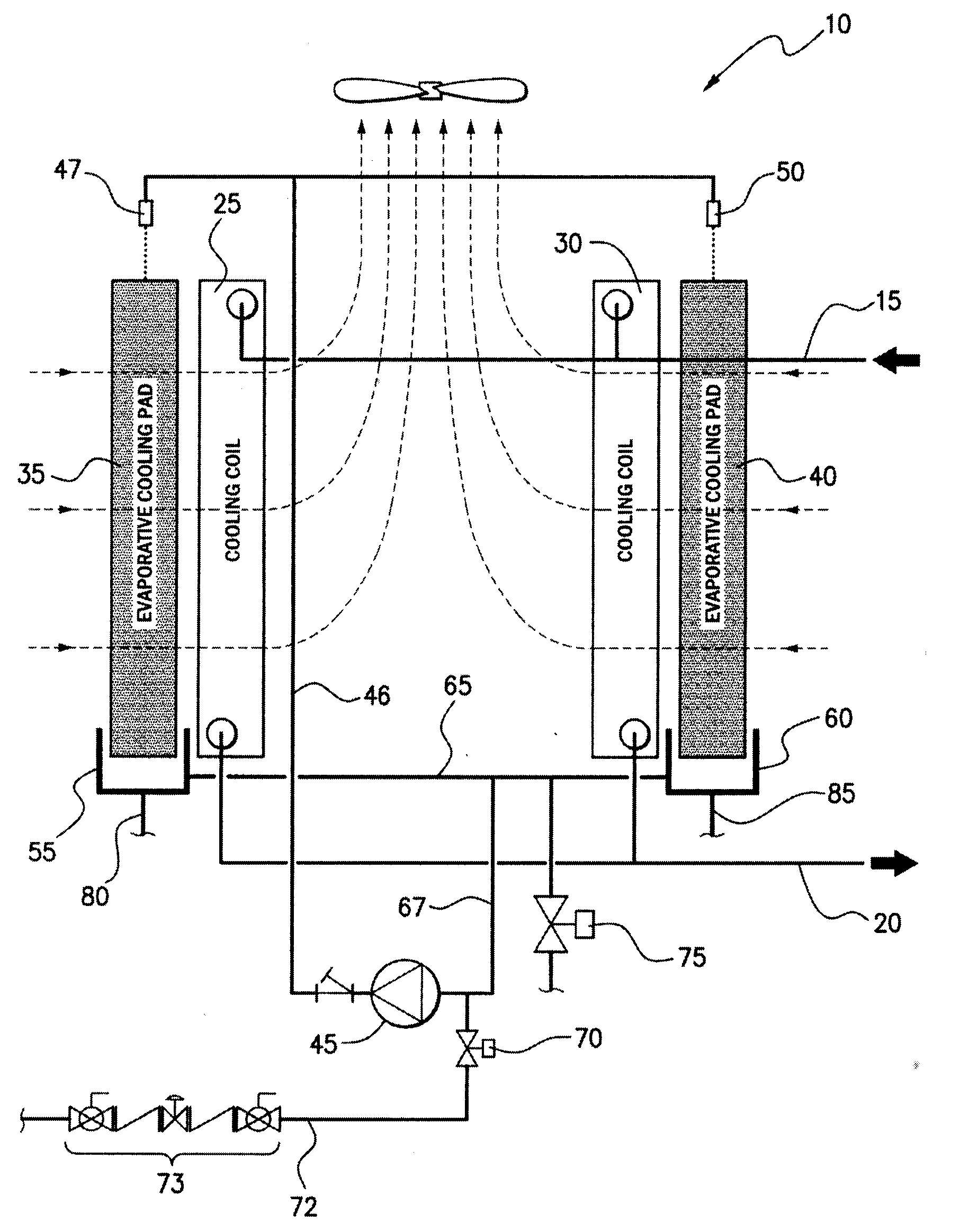
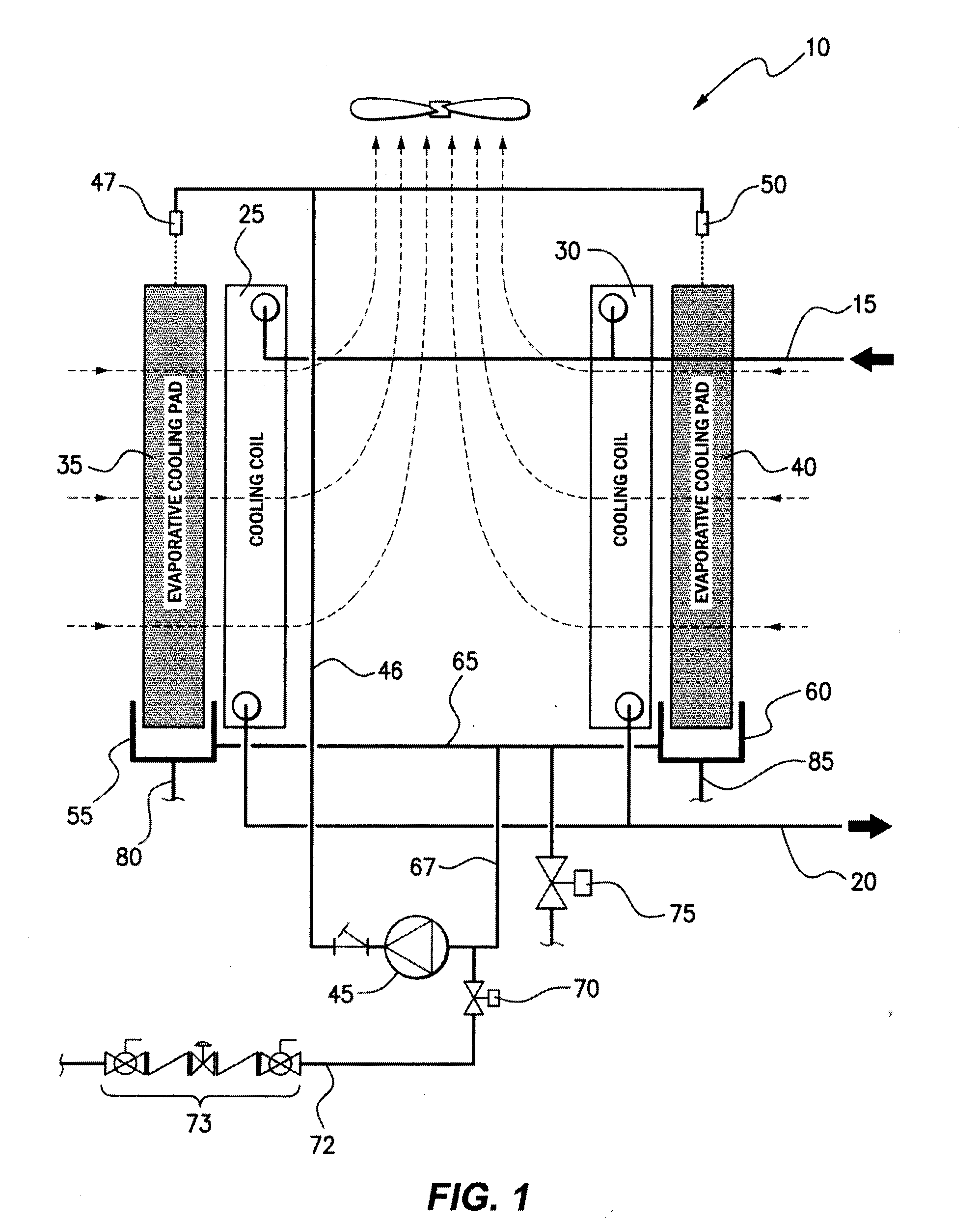
[0041]With reference to FIG. 1, a diagrammatic representation of an existing cooling system arrangement is provided wherein cooling fluid is passed through cooling coils (25, 30) through an inlet conduit (15) and subsequent to passing through the cooling coils (25, 30) is emitted through an outlet conduit (20). The cooling fluid may be water or a refrigerant fluid that is used to transfer thermal energy such as Freon. Further, where the cooling fluid is water, additives such as Glycol may be added to improve the thermal characteristics of the resulting cooling of fluid. The cooling fluid is supplied to the cooling coils (25, 30) through the inlet conduit (15) for the purpose of cooling the fluid and during the passage through the cooling coils (25, 30) thermal energy is extracted from the cooling fluid such that the fluid emitted through the outlet conduit (20) has a substantially lower temperature and hence may be returned to the cooling apparatus that uses the fluid for the purpos...


PUM


Abstract

A moisture recirculation system for evaporatively cooling air, the system including a moisture distribution arrangement which, in use, distributes moisture to an upper portion of moisture absorbent material; a trough disposed below the lower most portion of the moisture absorbent material for initially collecting moisture run-off; a sump in fluid communication with the trough for collecting and storing said run-off; and a pump in fluid communication with the sump which, in use, transfers moisture from the sump to the moisture absorbent material.

Description

FIELD[0001]The invention relates generally to a system and method of wetting adiabatic material for applications involving the evaporative cooling of air.BACKGROUND OF THE INVENTION[0002]Generally, in any cooling arrangement that employs adiabatic material for effecting the evaporative cooling of air, the adiabatic material is arranged substantially vertically. Moisture is deposited on an upper portion of the adiabatic material and by the force of gravity, the moisture gradually descends through the adiabatic material and is absorbed into the material.[0003]A sufficient amount of moisture is required to saturate the adiabatic material in order to achieve the maximum evaporative cooling effect possible that results from forcing air through the saturated adiabatic material. As air is forced through the adiabatic material, it is cooled by the action of evaporation. As this occurs, the amount of moisture absorbed into the adiabatic material reduces as the moisture in liquid form is vapo...

Claims


Application Information

Patent Timeline
Patent Type & Authority Applications(United States)
IPC IPC(8): F25D17/06F28D5/00
CPCF24F5/0035F24F6/043Y02B30/54
Inventor HALL, GRANT DAVIDDE JONG, ROBERT
Owner BALTIMORE AIRCOIL CO INC
Why Eureka
Try Eureka