Method for operating an internal combustion engine

a control device and internal combustion engine technology, applied in the direction of electric control, speed sensing governors, instruments, etc., can solve the problems of excessively high precontrolled torque, and unsatisfactory increase in torque output of internal combustion engines, so as to prevent an erroneous response of the torque monitor, reduce the needlessly high, pilot-controlled torque

a control device and internal combustion engine technology, applied in the direction of electric control, speed sensing governors, instruments, etc., can solve the problems of excessively high precontrolled torque, and unsatisfactory increase in torque output of internal combustion engines, so as to prevent an erroneous response of the torque monitor, reduce the needlessly high, pilot-controlled torque

US20100162996A1Inactive Publication Date: 2010-07-01ROBERT BOSCH GMBH

Image

  • Method for operating an internal combustion engine
  • Method for operating an internal combustion engine
  • Method for operating an internal combustion engine

Examples


Embodiment Construction

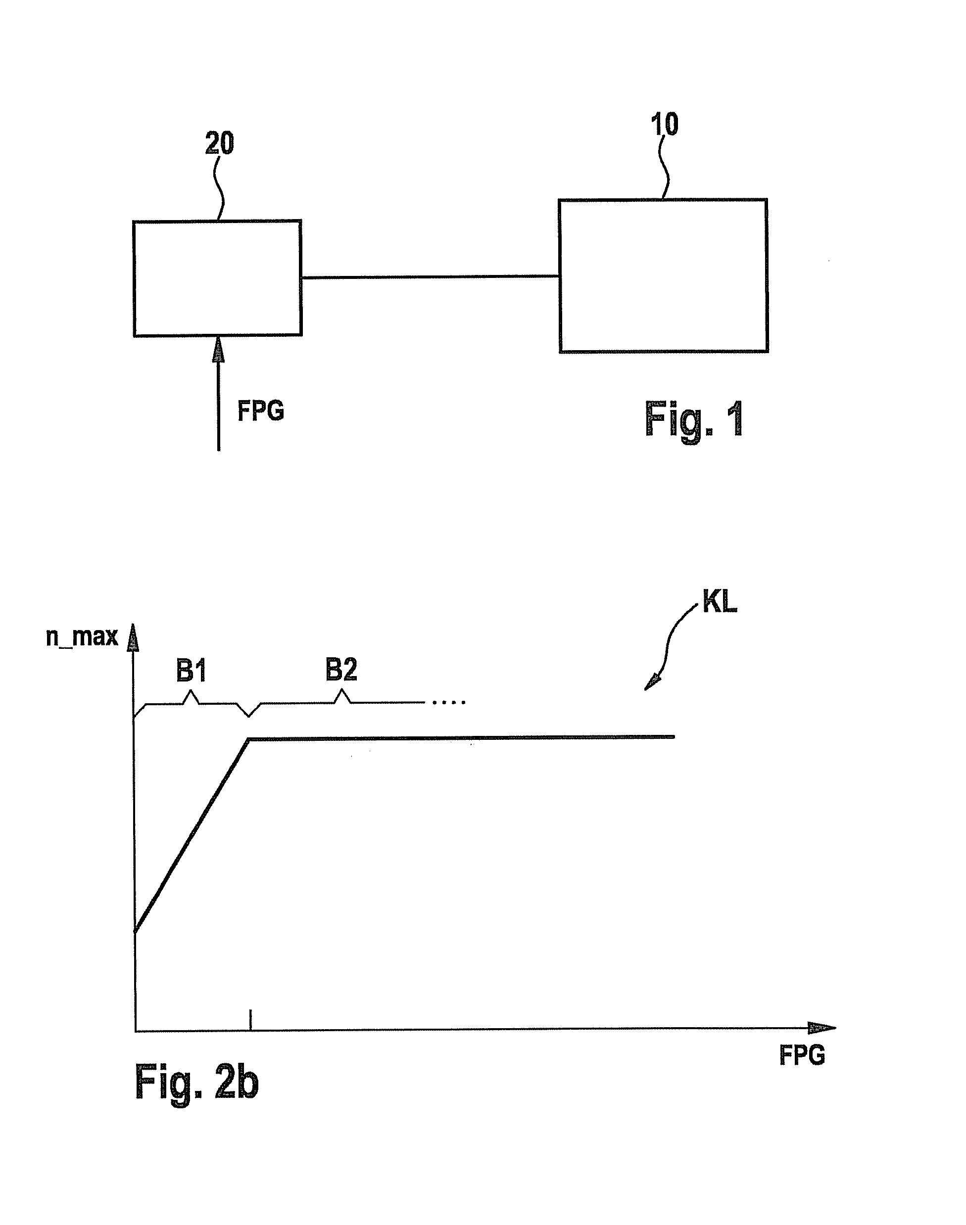
[0022]FIG. 1 schematically illustrates an internal combustion engine 10 whose operation is controlled and / or regulated with the aid of an associated control device 20.

[0023]As can be seen from FIG. 1, a signal FPG of an accelerator sensor is forwarded to control device 20, the signal representing a torque desired by a driver of the motor vehicle in which internal combustion engine 10 is installed.

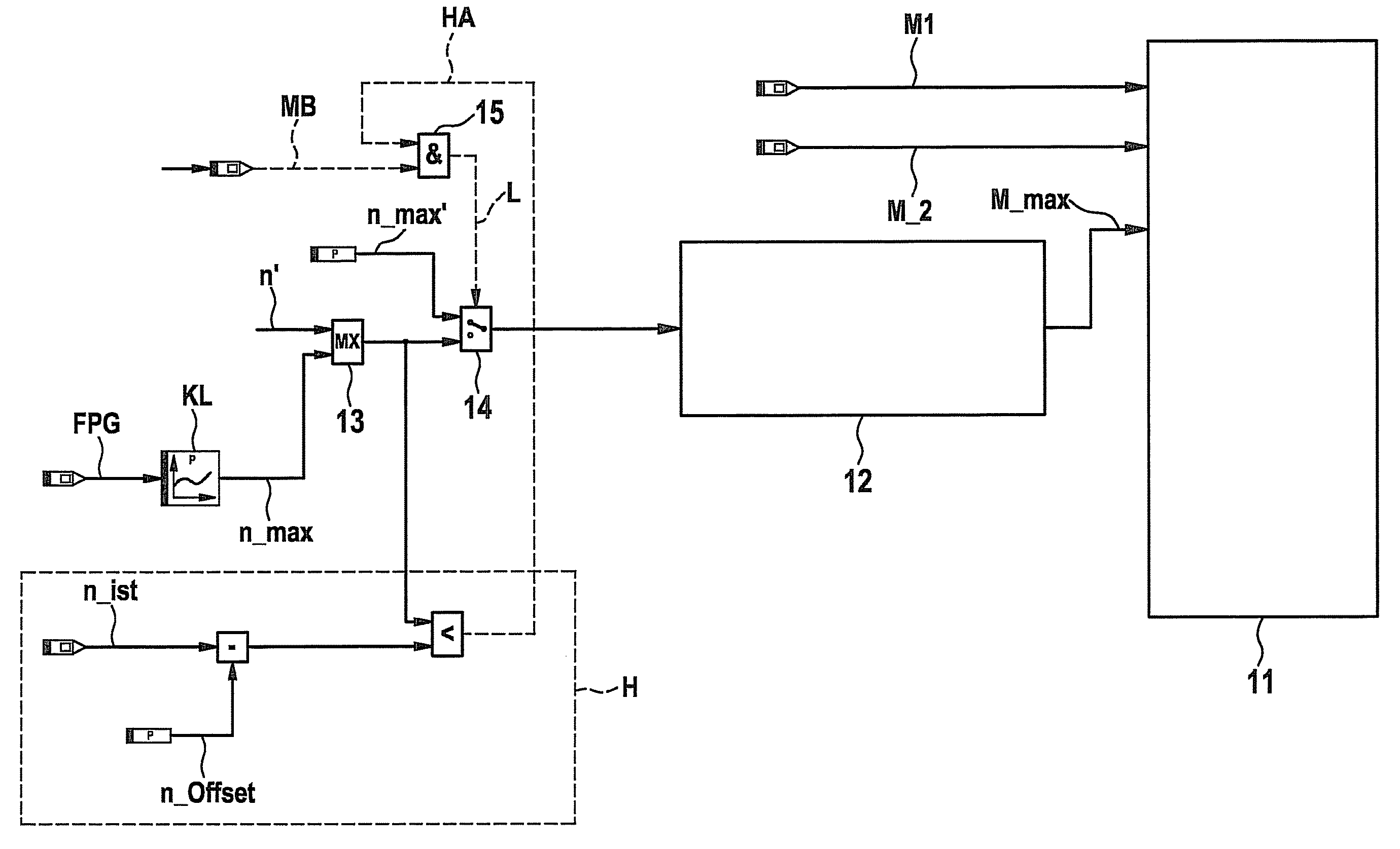
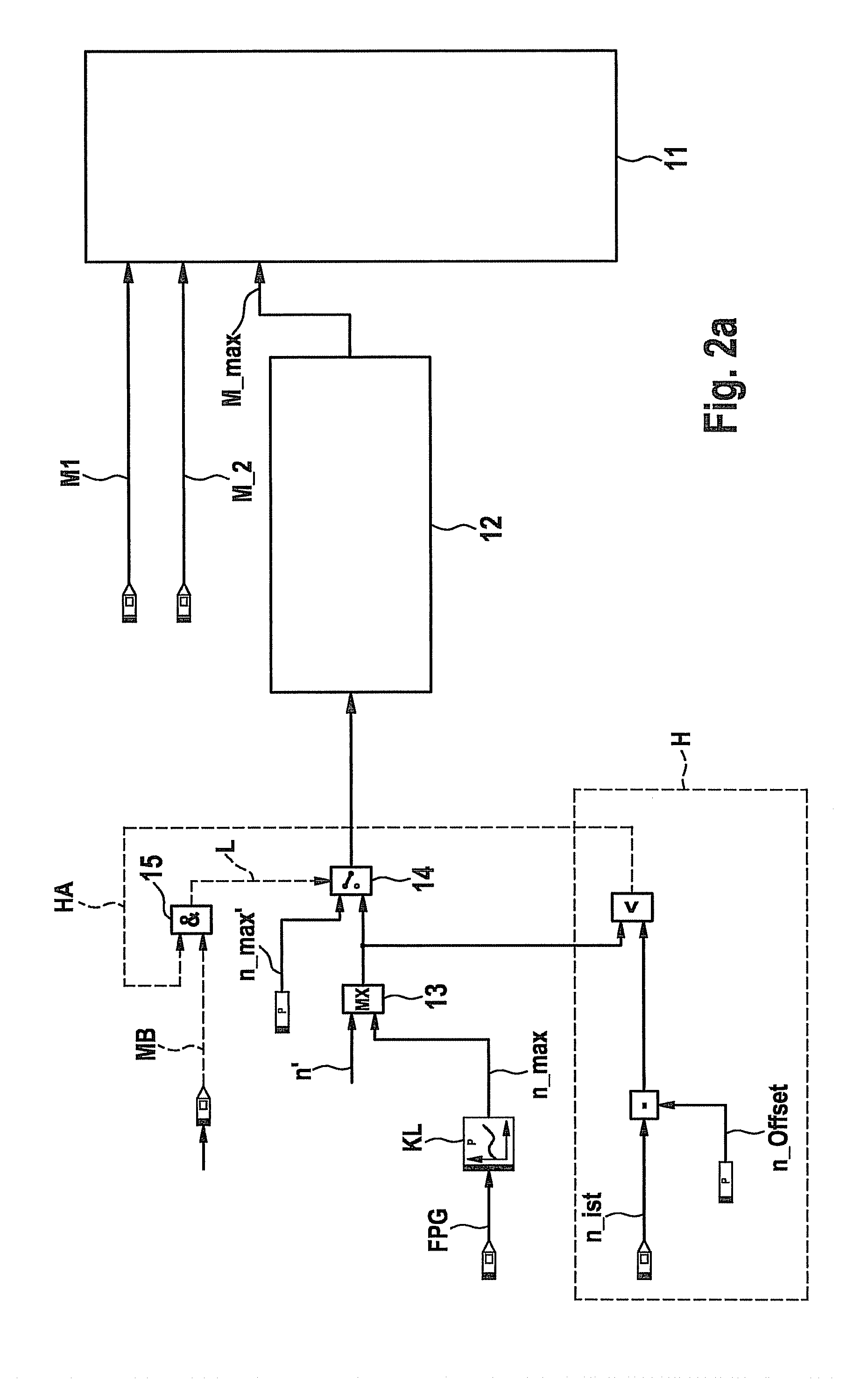
[0024]The example method according to the present invention provides a restriction of the setpoint torque to be output by internal combustion engine 10 to a specifiable torque, in particular in response to an error in the control of internal combustion engine 10, in order to prevent an undesired acceleration of internal combustion engine 10 as a result of torque-increasing errors in the control or control device 20.

[0025]FIG. 2a shows a flow chart for realizing a first specific embodiment of the example method according to the present invention, in which a setpoint torque correspondingly re...


PUM


Abstract

A method for operating an internal combustion engine, in which a setpoint torque to be output by the internal combustion engine is restricted to a specifiable torque, in particular in response to an error in the control of the internal combustion engine. An engine speed of the internal combustion engine is determined as a function of at least one performance quantity of the internal combustion engine, and the specifiable torque is modified as a function of the determined engine speed.

Description

FIELD OF THE INVENTION[0001]The present invention relates to a method and a control device for operating an internal combustion engine, in which a setpoint torque to be output by the internal combustion engine is restricted to a specifiable torque, in particular in response to an error in the control of the internal combustion engine.BACKGROUND INFORMATION[0002]Methods of the type mentioned above and used, for instance, within the framework of monitoring a torque actually output by the internal combustion engine. A restriction of the setpoint torque to be output by the internal combustion engine is provided especially when an error has been detected in the control of the internal combustion engine, which error causes an undesired increase in the torque output by the internal combustion engine.SUMMARY[0003]An object of the present invention to provide an improved method for operating an internal combustion engine.[0004]According to the present invention, this object may be achieved b...

Claims


Application Information

Patent Timeline
01 Jul 2010
Publication
US20100162996A1
IPC
F02D11/10
CPC
F02D11/107; F02D31/006; F02D41/22; Y02T10/40; F02D2250/18; F02D2250/26; F02D2041/227
Inventors
GWINNER, ROBERT; ESTEGHLAL, GHOLAMABAS