Multi-wire saw and method for cutting ingot
a multi-wire saw and ingot technology, which is applied in the field of multi-wire saws for cutting an, can solve the problems of increasing the probability of disengagement of the wire from the guide groove, chipping on the edge of the wafer, and increasing the probability of the wire being cut out of the guide groove, so as to improve the yield of non-defective wafers and reduce the thickness variation of the edges of the wafer cut out from the material to be machined
- Summary
- Abstract
- Description
- Claims
- Application Information
AI Technical Summary
Benefits of technology
Problems solved by technology
Method used
Image
Examples
first embodiment
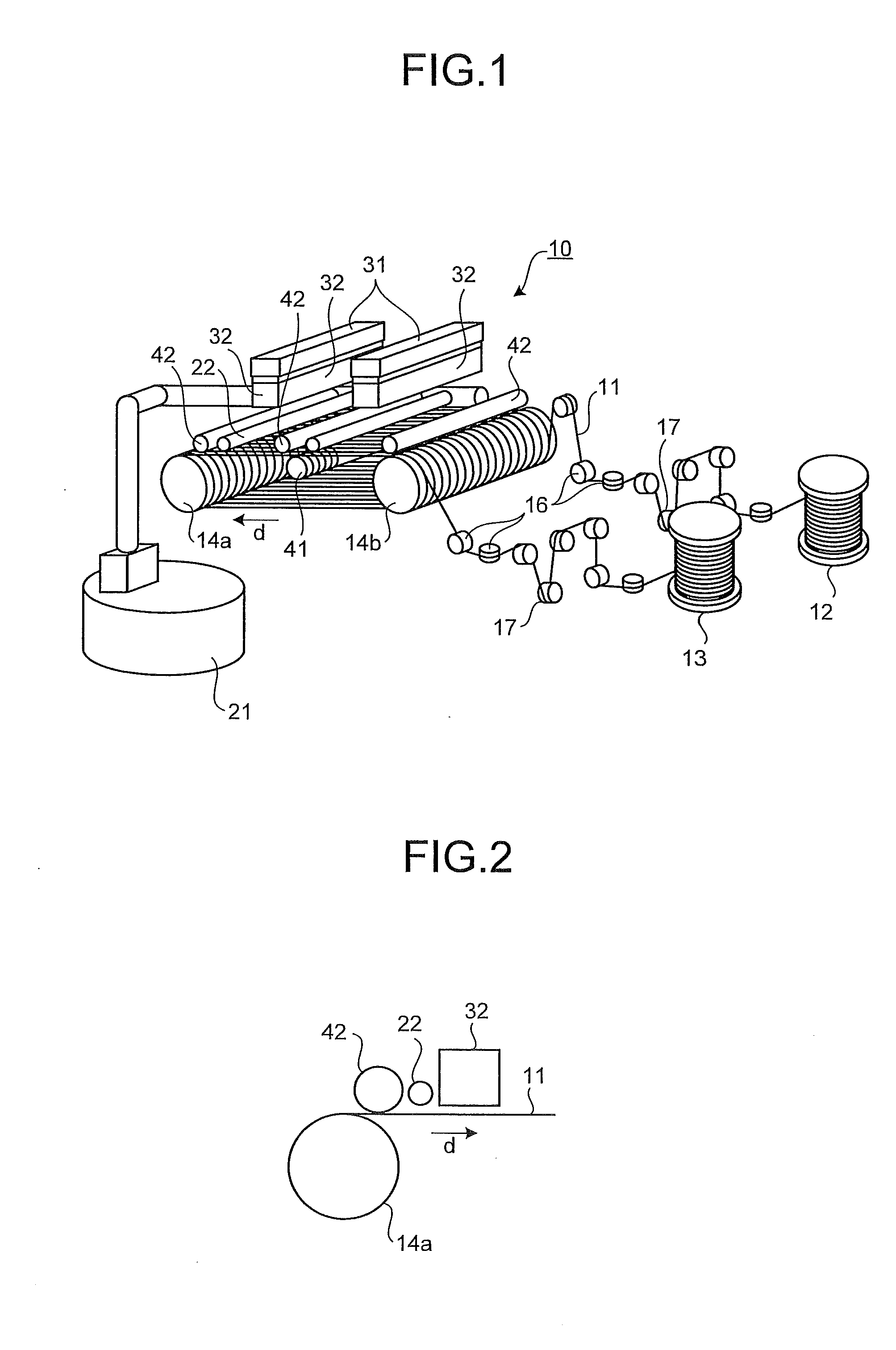
[0045]FIG. 1 is a perspective view showing a main part of a multi-wire saw according to the present invention, FIG. 2 is a side view of the structure near a wire guide roller seen from a direction of the rotation axis of the wire guide roller, and FIG. 3 is a schematic diagram showing a relationship between a wire restraining unit and the wire guide rollers.
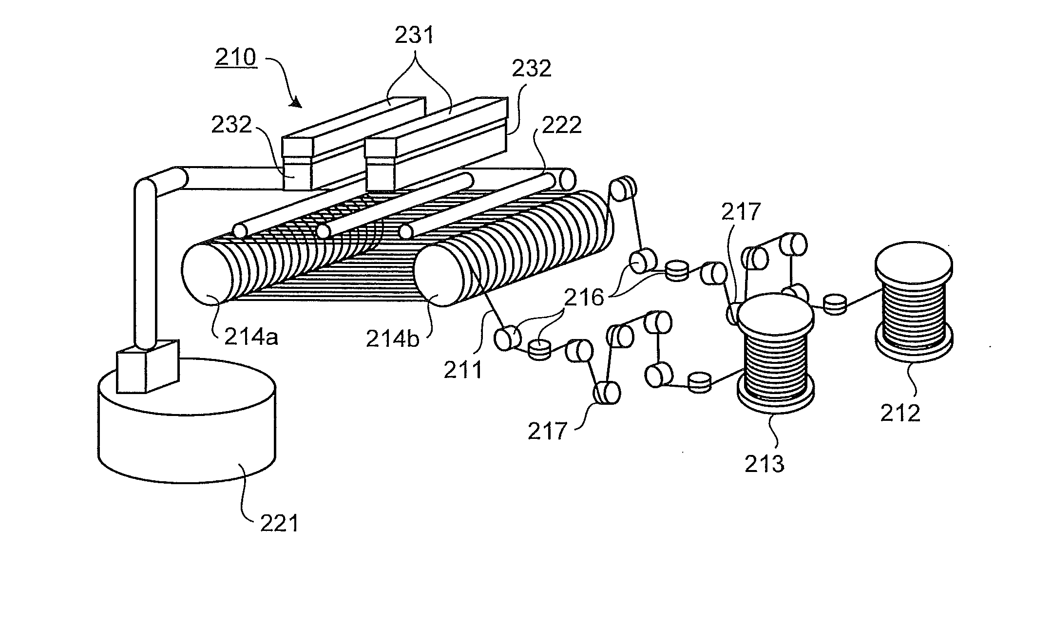
[0046]As illustrated in FIG. 1, a multi-wire saw 10 includes a wire 11; a wire-feeding mechanism 12 that feeds the wire 11; a wire winding-up mechanism 13 that winds up the fed wire 11; two wire guide rollers 14a and 14b that are disposed between the wire-feeding mechanism 12 and the wire winding-up mechanism 13 such that the rotation axes of the rollers are parallel to each other; a plurality of guide rollers 16 that guides the wire 11 traveling from the wire-feeding mechanism 12 to the wire guide roller 14a and guides the wire 11 from the wire guide roller 14b to the wire winding-up mechanism 13; and a tension roller 17 that co...
second embodiment
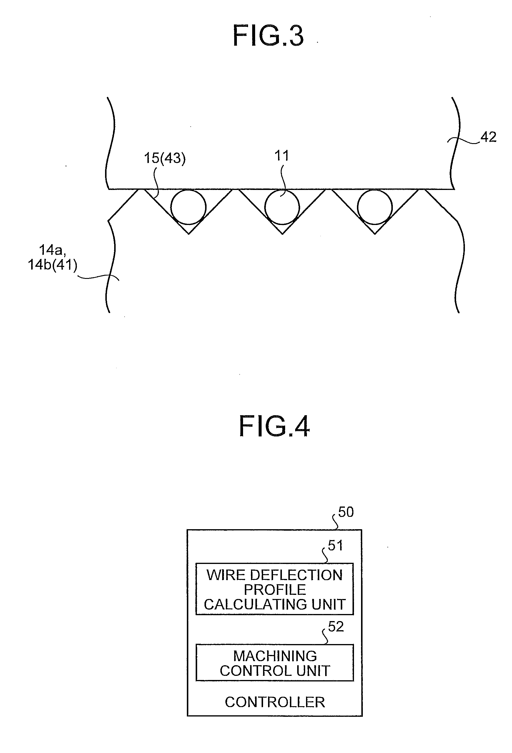
[0054]FIG. 4 is a functional block diagram showing a controller of the multi-wire saw. A controller 50 includes a wire deflection profile calculating unit 51, and a machining control unit 52. The configuration of the multi-wire saw 10 controlled by the controller 50 is the same as that of the first embodiment in FIG. 1, therefore, the explanation thereof will be omitted.
[0055]The wire deflection profile calculating unit 51 derives deflection of the wire 11 at a predetermined cutting position at the point where a depth of a kerf formed at the start of cutting of the ingots 32 is at least equal to or larger than the radius of the wire 11. FIG. 5 is a schematic sectional view showing a state of an ingot cut to a depth e at the start of cutting of the ingot, and FIG. 6 is a schematic diagram showing a state in which the multi-wire saw is seen from the direction of the rotation axes of the wire guide rollers at the start of cutting. In FIG. 5, a state in which the ingot 32 is cut to a de...
third embodiment
[0064]The wire-lifting restraining member 42 that prevents the wire 11 from being lifted, as described in the first and the second embodiments, may be a cylindrical body of rotation having a cylindrical surface with grooves at the same pitch as that of the guide grooves 15 and 43 formed on the wire guide rollers 14a, 14b, and 41.
[0065]According to a third embodiment, obtained is an effect of enabling the side run-out of the wire to be further suppressed at the moment of starting of cutting by forming the guide grooves on the surface of the wire-lifting restraining member 42, thereby further reducing the thickness variation of the edges of the wafers compared with a case where a cylindrical body of rotation having nothing formed on a surface thereof is used.
[0066]The effects when the ingot is cut with the multi-wire saw 10 according to the first, the second, and the third embodiments will be explained below. Experiments in cutting were conducted in three rounds for each of the follow...
PUM
| Property | Measurement | Unit |
|---|---|---|
| Thickness | aaaaa | aaaaa |
| Thickness | aaaaa | aaaaa |
| Thickness | aaaaa | aaaaa |
Abstract
Description
Claims
Application Information
 - R&D
- Intellectual Property
- Life Sciences
- Materials
- Tech Scout
- Unparalleled Data Quality
- Higher Quality Content
- 60% Fewer Hallucinations
Browse by: Latest US Patents, China's latest patents, Technical Efficacy Thesaurus, Application Domain, Technology Topic, Popular Technical Reports.
© 2025 PatSnap. All rights reserved.Legal|Privacy policy|Modern Slavery Act Transparency Statement|Sitemap|About US| Contact US: help@patsnap.com


