Fluid apparatus unit structure

a technology of fluid apparatus and unit structure, which is applied in fluid dynamics, valve housings, transportation and packaging, etc., can solve the problems of slurred chemical fluid that will readily solidify when it pools, and achieve the effect of facilitating displacing and flushing out of chemical fluid by water and reducing the length of the flow path

Active Publication Date: 2010-07-01
SURPASS IND
View PDF11 Cites 8 Cited by
  • Summary
  • Abstract
  • Description
  • Claims
  • Application Information

AI Technical Summary

Benefits of technology

[0019]According to such a fluid apparatus unit structure, because the flow path for chemical fluid circulation is formed via the valve body accommodating spaces of the valves that have been disposed in the flow path for water circulation, the length of the flow path can be reduced.
[0020]In this case, preferably, valves are provided with a plug-type valve body in the valve body accommodation space, and the water circulation circuit communicates with the bottom of the valve body. The displacing and flushing out of the chemical fluid by water is thereby facilitated.
[0021]According to the fluid apparatus unit structure of the present invention described above, the for

Problems solved by technology

However, in a fluid apparatus unit structure in which the chemical fluid can be removed as necessary while carrying out the chemical flu

Method used


Image

  • Fluid apparatus unit structure
  • Fluid apparatus unit structure
  • Fluid apparatus unit structure

Examples


Embodiment Construction

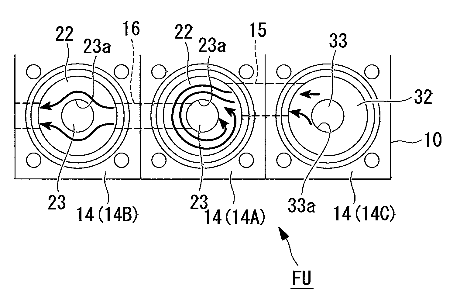
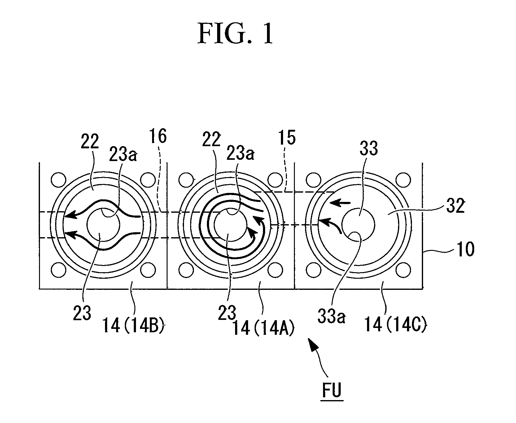
[0029]Below, an embodiment of the fluid apparatus unit structure according to the present invention will be explained with reference to the figures.

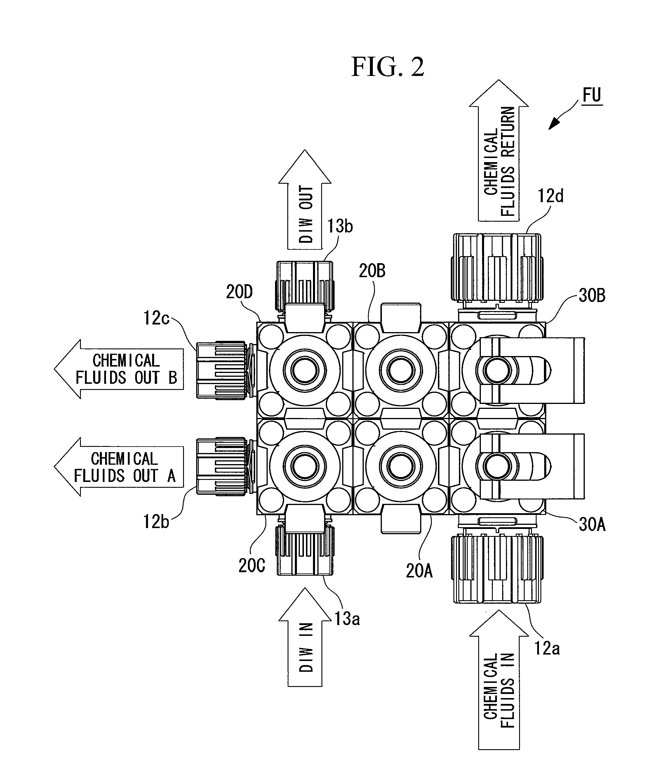
[0030]The structure of the fluid apparatus unit FU that is shown in FIG. 2 to FIG. 5 is one in which plural fluid apparatus components that are connected via the flow path are grouped together and integrated into a base member 10. In the illustrated example of the structure, the main portions of the fluid apparatus unit 1 are made of a chemical-resistant fluorocarbon resin, four air pressure control valves 20A, 20B, 20C, and 20D and two manual control valves 30A and 30B serve as fluid apparatus components, and these fluid apparatus components are grouped together and integrated into a base member 10. The reference numeral 11 in the figures indicates a base fastening plate.

[0031]FIG. 3 shows the flow path (circuit) structure of a fluid apparatus unit FU, and in this example of a flow path structure, a first air pressure control valve 20A ...


PUM


Abstract

A fluid apparatus unit structure is provided that can be applied to a use in which a chemical fluid is removed as necessary while chemical fluid circulation and water circulation are being carried out, a fluid such as a chemical fluid does not readily solidify therein, and the fluid apparatus unit structure is compact. In the fluid apparatus unit structure (FU) that groups together and integrates plural fluid apparatus components that are connected via a flow path into a base member (10), a linked flow path (15), which links an adjacent air pressure control valve (20A) and a manual control valve (30A) that form a first chemical fluid discharge path that carries out chemical fluid circulation, is offset from the axial center of the fluid apparatus components.

Description

TECHNICAL FIELD[0001]The present invention relates to a fluid apparatus unit structure that integrates fluid apparatus components such as valves and pressure switches.BACKGROUND ART[0002]Conventionally, apparatuses that handle fluids (chemical fluids) such as pharmaceuticals are formed as a fluid apparatus unit structure (an integrated structure) in which the various types of fluid apparatus components (valves, regulators, various sensors such as pressure sensors, and various switches such as pressure switches), which form the constituent elements, are integrated by being connected by piping. Such fluid apparatus unit structures include those in which a chemical fluid is removed as necessary while carrying out slurried chemical fluid circulation and water circulation.[0003]In addition, in the case in which, for example, plural fluid apparatuses for chemical fluids are used, such as in semiconductor manufacturing equipment, an integrated structure that enables fluid apparatuses for c...

Claims


Application Information

Patent Timeline
IPC IPC(8): F15D1/00
CPCF16K27/003Y10T137/87249F16K27/00F16K27/06F16J15/06F16L17/06
Inventor IGARASHI, HIROKI
Owner SURPASS IND
Why Eureka
Try Eureka