Disk brake

a technology of brakes and disks, applied in the direction of brake systems, friction linings, transportation and packaging, etc., can solve the problems of poor responsiveness of above-mentioned conventional art, and achieve the effect of poor responsiveness and excellent responsiveness

Inactive Publication Date: 2010-07-01
HITACHI AUTOMOTIVE SYST LTD
View PDF5 Cites 39 Cited by
  • Summary
  • Abstract
  • Description
  • Claims
  • Application Information

AI Technical Summary

Benefits of technology

[0003]Disadvantageously, the above-mentioned conventional art has poor responsiveness due to use of a worm speed reducer f...

Problems solved by technology

Disadvantageously, the above-mentioned conventional art has poor respon...

Method used


Image

  • Disk brake
  • Disk brake
  • Disk brake

Examples


first embodiment

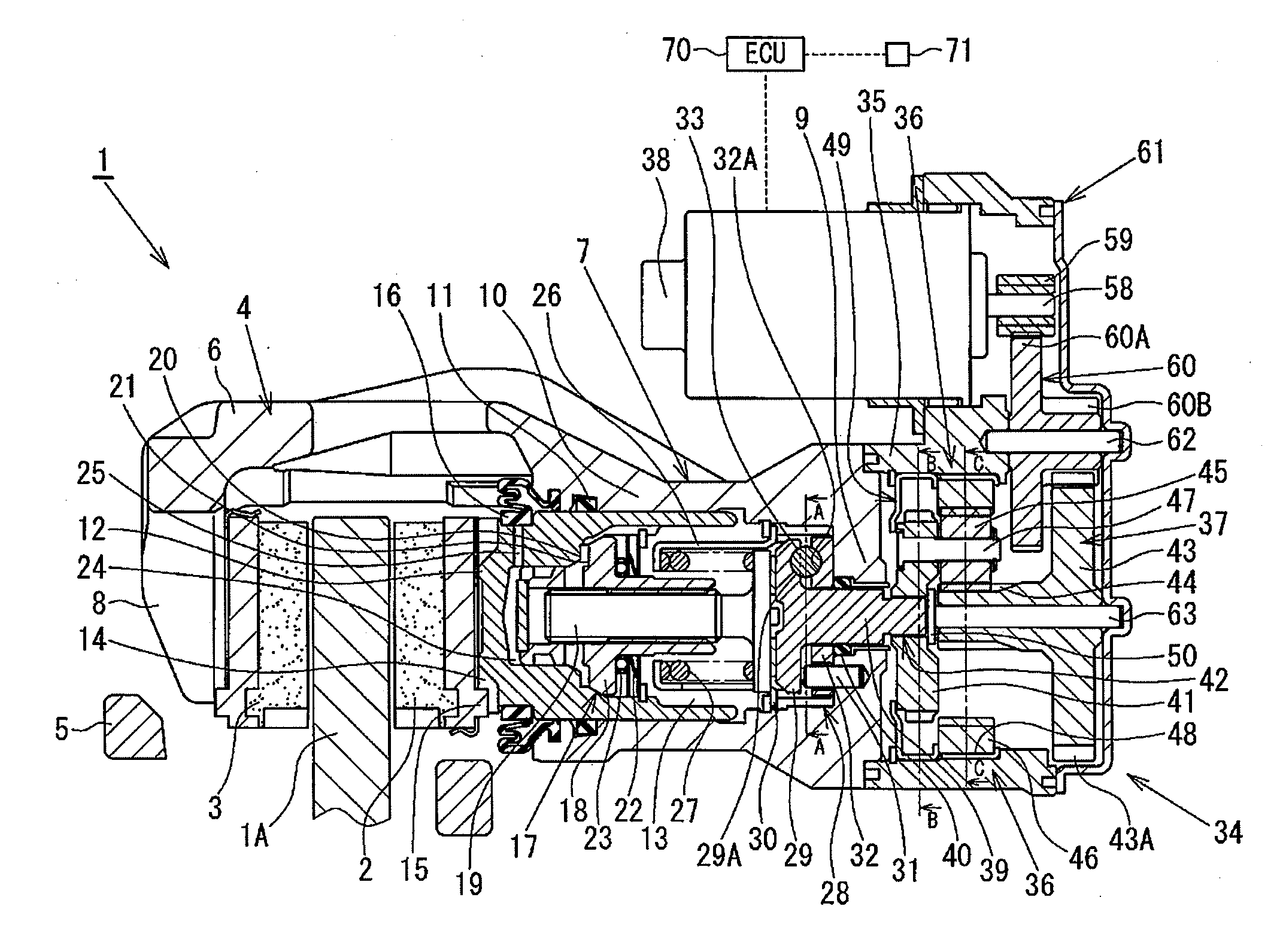
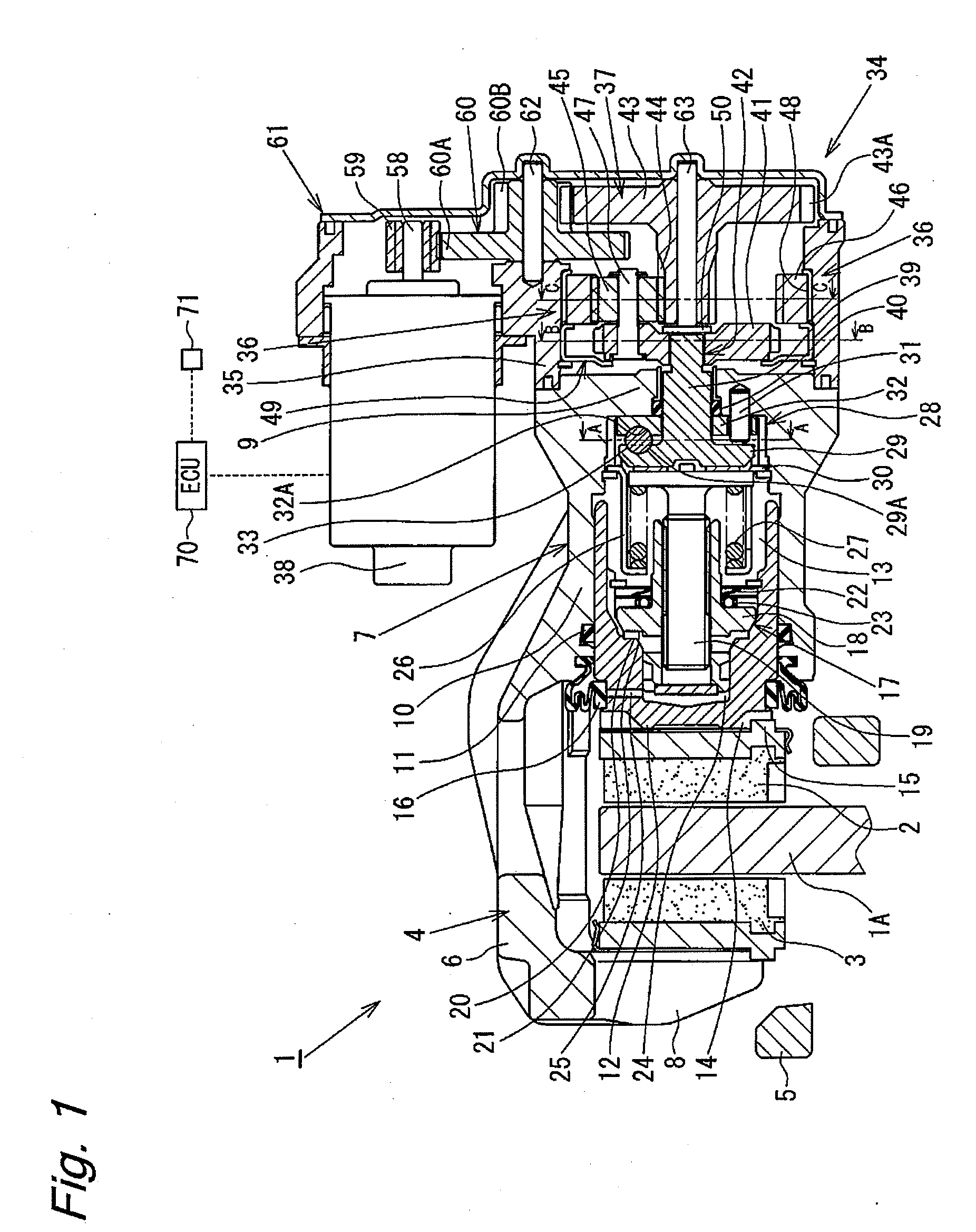
[0032]Hereinafter, a disk brake will be described with reference to FIGS. 1 to 11B. FIGS. 1 and 2 show a disk brake 1 according to the present embodiment. In FIGS. 1 and 2, reference numerals 2 and 3 denote a pair of brake pads disposed on the respective sides of a disk rotor 1A attached to a rotational portion of a vehicle so as to sandwich the disk rotor 1A therebetween, and reference numeral 4 denotes a caliper. The disk brake 1 is configured as a floating caliper type disk brake. The pair of brake pads 2 and 3, and the caliper 4 are supported by a carrier 5 fixed to a non-rotational portion of the vehicle such as a knuckle so as to be movable in the axial direction of the disk rotor 1A.

[0033]A caliper body 6, which is a main body of the caliper 4, comprises a cylinder portion 7 and a claw portion 8. The cylinder portion 7 is formed at the proximal end side of the caliper body 6 which faces the inner pad 2 or the brake pad of the inner side of the vehicle, and the claw portion 8...

fifth embodiment

[0083]As shown in FIG. 26, in the fifth embodiment, a shutter 80 is disposed adjacent to the carrier 41 so as to be extremely close but non-contactable to the carrier 41. The shutter 80 is rotatably supported by a sleeve 81 fixed to the bottom wall 9 of the cylinder portion 7. A disc spring 82 is disposed between the shutter 80 and the bottom wall 9 of the cylinder portion 7, and urges the shutter 80 toward a flange 81A of the sleeve 81. Therefore, a certain resistance (also referred to as “rotational resistance” as appropriate) is applied to a rotation of the shutter 80

[0084]As shown in FIGS. 27 and 28B, the shutter 80 generally comprises a disk-shaped stepped shutter body 80H having a hole (not labeled) at the center thereof, and a plurality of protrusions 80A formed along the outer circumference of the shutter body 80H. The protrusions 80A are formed so as to radially outwardly extend from the shutter body 80H. In the present embodiment, when the protrusions 80A are situated to p...

fourth embodiment

[0115]In the above-mentioned fourth embodiment, the rotation / linear motion converting mechanism is a screw mechanism.

[0116]In the above-mentioned embodiments, the electric motor is controlled by a controller for driving the electric motor based on a maintaining signal or a releasing signal from a parking brake instruction unit. The controller starts to drive the electric motor based on the maintaining signal from the parking brake instruction unit, and stops the electric motor after the electric motor shows an electric current value causing the piston to be situated at the parking brake applying position, whereby the rotation preventing mechanism prevents a rotation of the one output member.

[0117]In the above-mentioned embodiments, the controller starts to drive the electric motor in the direction causing the piston to return based on the releasing signal from the parking brake instruction unit, and stops the electric motor based on an electric current value of the electric motor.

[0...


PUM


Abstract

An object of the present invention is to provide a disk brake having excellent responsiveness. A rotation preventing mechanism 34A prevents a rotation of a carrier 41 (one output member) in a direction causing a piston 12 to return. An internal gear 46 (the other output member) rotates by a predetermined degree to act on the rotation preventing mechanism 34A. When the motor 38 causes a sun gear (input member) to rotate such that the piston 12 moves in a return direction, a rotation of the internal gear 46 according to the rotation of the sun gear 44 releases rotation prevention of the rotation preventing mechanism 34A to the carrier 41. It is possible to release the parking brake without use of a worm gear which is used in the conventional arts for holding a thrust force (self-holding). As a result, it is possible to quickly release the parking brake, and therefore a driver can start to run without delay after parking brake release, whereby the responsiveness is improved.

Description

BACKGROUND OF THE INVENTION[0001]The present invention relates to a disk brake for use in braking a vehicle.[0002]Some disk brakes employ a worm speed reducer for self-holding of a brake force to realize the parking brake function (refer to Japanese Patent Application Public Disclosure No. 2006-177532).SUMMARY OF THE INVENTION[0003]Disadvantageously, the above-mentioned conventional art has poor responsiveness due to use of a worm speed reducer for self-holding of a brake force. One object of the present invention is to provide a disk brake having excellent responsiveness.[0004]According to one aspect of the present invention is a disk brake comprising:[0005]a pair of pads disposed on the respective sides of a disk;[0006]a piston adapted to press at least one of the pair of pads against the disk;[0007]a caliper body including a cylinder capable of containing the piston such that the piston is movable in the cylinder, the caliper body adapted to advance the piston by a supply of a fl...

Claims


Application Information

Patent Timeline
IPC IPC(8): B60T8/72F16D65/18
CPCB60T7/107B60T7/122B60T13/741F16D65/18F16D2121/02F16D2121/24F16D2123/00F16D2125/36F16D2125/40F16D2125/48F16D2125/50F16D2127/06
Inventor SAKASHITA, TAKAYASUWATANABE, JUN
Owner HITACHI AUTOMOTIVE SYST LTD
Why Eureka
Try Eureka