Projection system and control method of projection system

a projection system and control method technology, applied in the field of projection systems, can solve the problems of no consideration of color mixing, and achieve the effect of preventing darkening of displays and poor responsiveness of light modulation elements

Pending Publication Date: 2022-08-18
SONY CORP
View PDF9 Cites 0 Cited by
  • Summary
  • Abstract
  • Description
  • Claims
  • Application Information

AI Technical Summary

Benefits of technology

[0005]According to an existing technology described in the above PTL 1, it is possible to prevent darkening of display in performing sequential color display. However, in the existing technology, no consideration is given to color mixing resulting from poor responsiveness of a light modulation element.

Problems solved by technology

However, in the existing technology, no consideration is given to color mixing resulting from poor responsiveness of a light modulation element.

Method used


Image

  • Projection system and control method of projection system
  • Projection system and control method of projection system
  • Projection system and control method of projection system

Examples


example 1

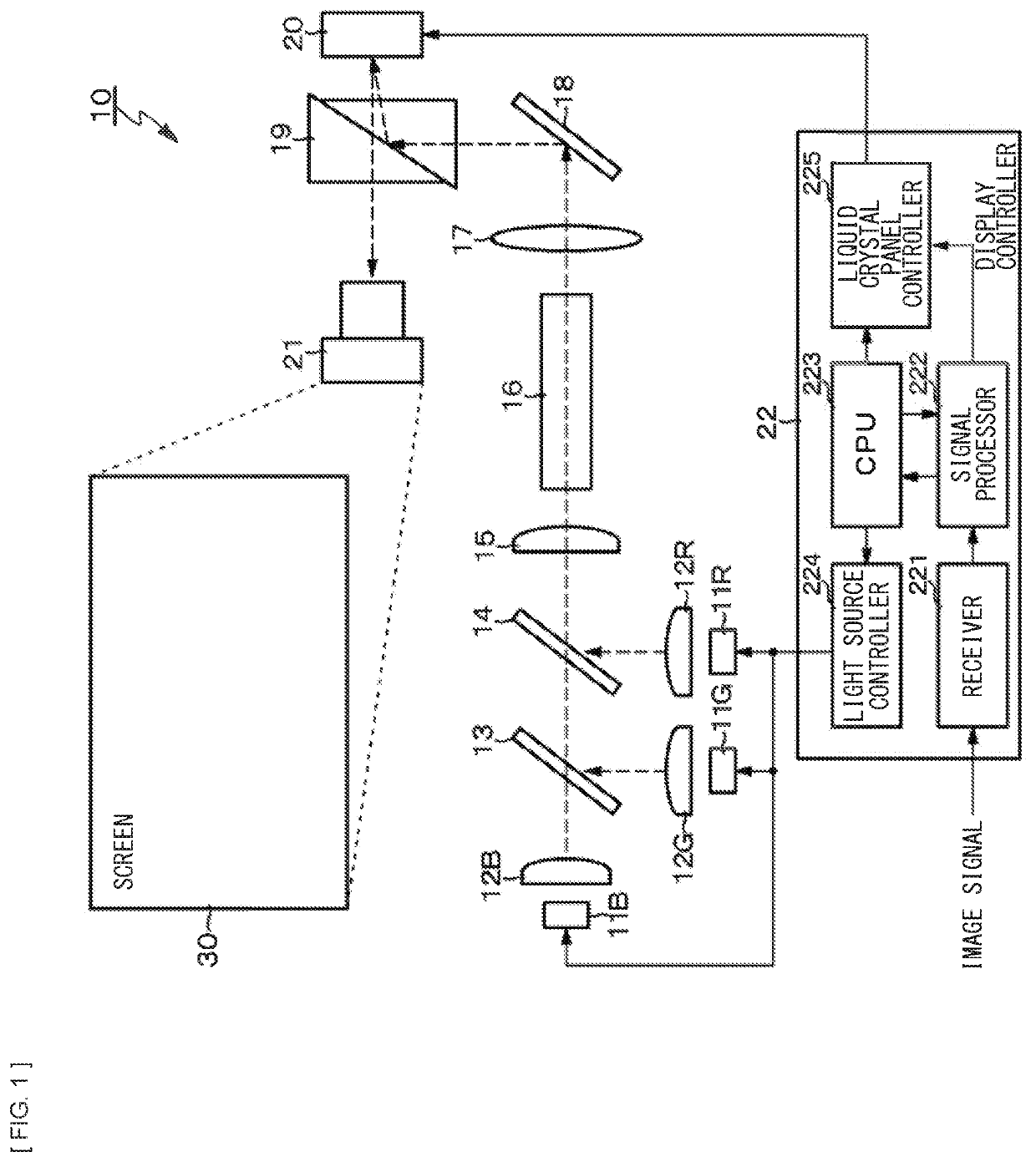
[0073]An example 1 is a system configuration example of a single-panel type projection system according to the embodiment of the present disclosure. FIG. 4 is a system configuration diagram of the single-panel type projection system according to the example 1.

[0074](System Configuration)

[0075]A projection system 10 according to the example 1 includes a light source (light source unit) 41, an image processing engine 42, a system controller 43, and a light source driving section 44, in addition to an optical system including the rod integrator 16 and the like, the liquid crystal panel 20, and a projection optical system including the projection lens 21.

[0076]The light source 41 includes, for example, the solid-state light sources 11R, 11G, and 11B that respectively output (emit) light of R (red), G (green), and B (blue) as a plurality of colors, and lenses 12R, 12G, and 12B respectively provided corresponding to the solid-state light sources 11R, 11G, and 11B. For example, any light s...

example 2

[0085]An example 2 is a modification example of the example 1, and is an example in which light source control is performed in consideration of a temperature (a panel temperature) of the liquid crystal panel 20. FIG. 6 illustrates a system configuration example of a projection system according to the example 2.

[0086](System Configuration)

[0087]Responsiveness of the liquid crystal panel 20 is changed by an influence of temperature dependence of the liquid crystal panel 20. Accordingly, in the projection system 10 according to the example 2, in consideration of the temperature of the liquid crystal panel 20, under control by the light source controller 431, control is performed to drive the light source 41 at a driving timing having a phase difference corresponding to the temperature of the liquid crystal panel 20 with respect to a driving timing of the liquid crystal panel 20.

[0088]Specifically, as illustrated in FIG. 6, the projection system 10 according to the example 2 includes a ...

example 3

[0095]An example 3 is a modification example of the example 1, and is an example in which an interval of light source control in the time-axis direction is variable. FIG. 9 illustrates an explanatory diagram about the interval of light source control according to the example 3.

[0096]In the example 1, the interval of light source control in a case where light output of the light source 41 is controlled in the time-axis direction in a stepwise manner is equal. In contrast, in the example 3, the interval of light source control in a case where light output of the light source 41 is controlled in the time-axis direction in a stepwise manner is variable. More specifically, as illustrated in FIG. 9, in the example 3, in a case where light output of the light source 41 is controlled in the time-axis direction in a stepwise manner, the interval of the light source control is narrower in a region X in which change in the response waveform of the liquid crystal panel 20 is steep than in a reg...


PUM


Abstract

A projection system of the present disclosure includes: a light source that outputs light of a plurality of colors; a display panel that includes a light modulation element provided for each pixel, and modulates the light outputted from the light source; a projection optical system that projects light having passed through the display panel; and a controller that controls light output of each color of the light source in a time-axis direction. This configuration is adopted to achieve an improvement in brightness of a projected image / a screen and prevention of color mixing in field sequential driving.

Description

TECHNICAL FIELD[0001]The present disclosure relates to a projection system (a projector / a projection type display device) and a control method of a projection system.BACKGROUND ART[0002]In projection systems, displaying methods for display panels include a plane division method and a field sequential method (a field color sequential method). The plane division method is a method of performing full-color display by spatially displaying three primary colors of R (red), G (green), and B (blue) and spatially mixing these colors. The field sequential method is a method of performing full-color display by temporally and sequentially displaying images of R, G, and B and temporally mixing the images. The field sequential method makes it possible to obtain brighter images as compared with spatial plane division (the plane division method).[0003]Incidentally, in a case where color sequential driving is performed in a field sequential (time division) manner, poor responsiveness of a light modu...

Claims


Application Information

Patent Timeline
Patent Type & Authority Applications(United States)
IPC IPC(8): G03B21/20G03B21/00
CPCG03B21/206G03B21/2053G03B21/2006G03B21/006G02F1/13G09G3/20G09G3/34G09G3/36H04N5/74H04N9/31G03B33/08
Inventor YAGI, MASATO
Owner SONY CORP
Why Eureka
Try Eureka