High pressure discharge lamp, high pressure discharge lamp electrode, method of producing the high pressure discharge lamp electrode, and illumination device and image display apparatus respectively using the high pressure discharge lamps

a technology of high pressure discharge and lamp electrode, which is applied in the direction of gas discharge lamp details, electrical discharge tubes, electrical apparatus, etc., can solve the problems of unstable shape of the solidified end of the electrode rod, shorten the life of the lamp, and achieve the effect of preventing blackening

Inactive Publication Date: 2002-12-10
PANASONIC CORP
View PDF23 Cites 10 Cited by
  • Summary
  • Abstract
  • Description
  • Claims
  • Application Information

AI Technical Summary

Benefits of technology

is to provide a high pressure discharge lamp that can prevent blackening, a high pressure discharge lamp electrode whose end does not need to be machined after melting, a method of producing the high pressure discharge lamp electrode, and an illumination device and an image display apparatus respectively using the high pressure discharge lamps.

Problems solved by technology

As a result of this high temperature of the electrode end, even though halogen substance has been inserted in the light-emitting part, tungsten used for making the electrode is deposited on an inner surface of the discharge tube, causing blackening.
This gives rise to a problem that a lamp life is shortened.
However, after an acute analysis, the inventor of the present invention found that various problems could arise if actually producing electrodes using the methods disclosed in the cited references.
As a result, the shape of the solidified end of the electrode rod was unstable in most cases and had to be machined to form an appropriate shape through such as polishing and grinding.
Additionally, the inventor found that blackening could not be adequately prevented in an actual use.
As a result, the shape of the solidified end of the electrode rod was not suitable for the actual use.
In this case, the inventor found that there might be a case where blackening could not adequately be prevented.
This leads to overheating of the electrode end in the actual use, meaning that blackening caused by the deposition of tungsten cannot be prevented.

Method used


Image

  • High pressure discharge lamp, high pressure discharge lamp electrode, method of producing the high pressure discharge lamp electrode, and illumination device and image display apparatus respectively using the high pressure discharge lamps
  • High pressure discharge lamp, high pressure discharge lamp electrode, method of producing the high pressure discharge lamp electrode, and illumination device and image display apparatus respectively using the high pressure discharge lamps
  • High pressure discharge lamp, high pressure discharge lamp electrode, method of producing the high pressure discharge lamp electrode, and illumination device and image display apparatus respectively using the high pressure discharge lamps

Examples


first embodiment

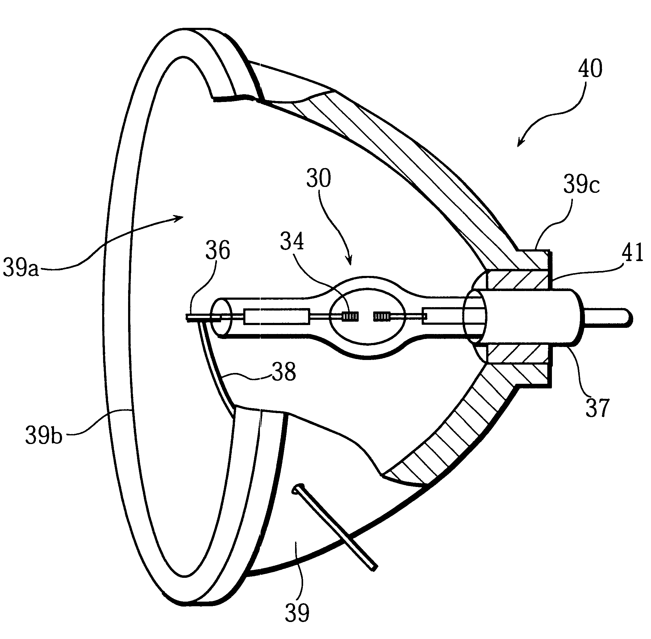
FIG. 4 is a front view showing a construction example of a high pressure mercury lamp 10 that is taken as an example of the high pressure discharge lamp related to the present invention. As shown in this figure, the high pressure mercury lamp 10 is provided with a discharge tube 11 that is made of quartz glass with its. middle part in the direction of the length being spheroid. The discharge tube 11 includes a light-emitting part 12 and a pair of sealing parts 13. A sealing part 13 is positioned at both ends of the light-emitting part 12. The maximum internal diameter of the central part of the light-emitting part 12 is 7.0 mm, the capacity of the light-emitting part 12 is 0.24 cm.sup.3, and the wall thickness is 2.5 mm. The light-emitting part 12 includes a pair of electrodes 14 facing each other, with a length between the discharge side tips of these electrodes 14 (this length is referred to as the "arc length" hereinafter) being 1.55 mm. The light-emitting part 12 is filled with ...

second embodiment

In the first embodiment, the electrode around which the coil has been provided beforehand is extended into the discharge tube, and then the end of the electrode is integrally melted during the initial discharge taken place when the high pressure mercury lamp is lit up for the first time. However, as explained in detail in the first embodiment, the changes in the arc length can be suppressed by defining the length .DELTA.L of the end of the electrode rod that is left uncovered with the coil. This is to say, by defining the length .DELTA.L in the same way as described, the stated problems in the prior art can be also solved when only high pressure discharge lamp electrodes are manufactured.

Accordingly, a description is given in the present embodiment for a case where electrodes are independently manufactured. Therefore, contrary to the first embodiment, an electrode is fully formed before being extended into a discharge tube in the present embodiment.

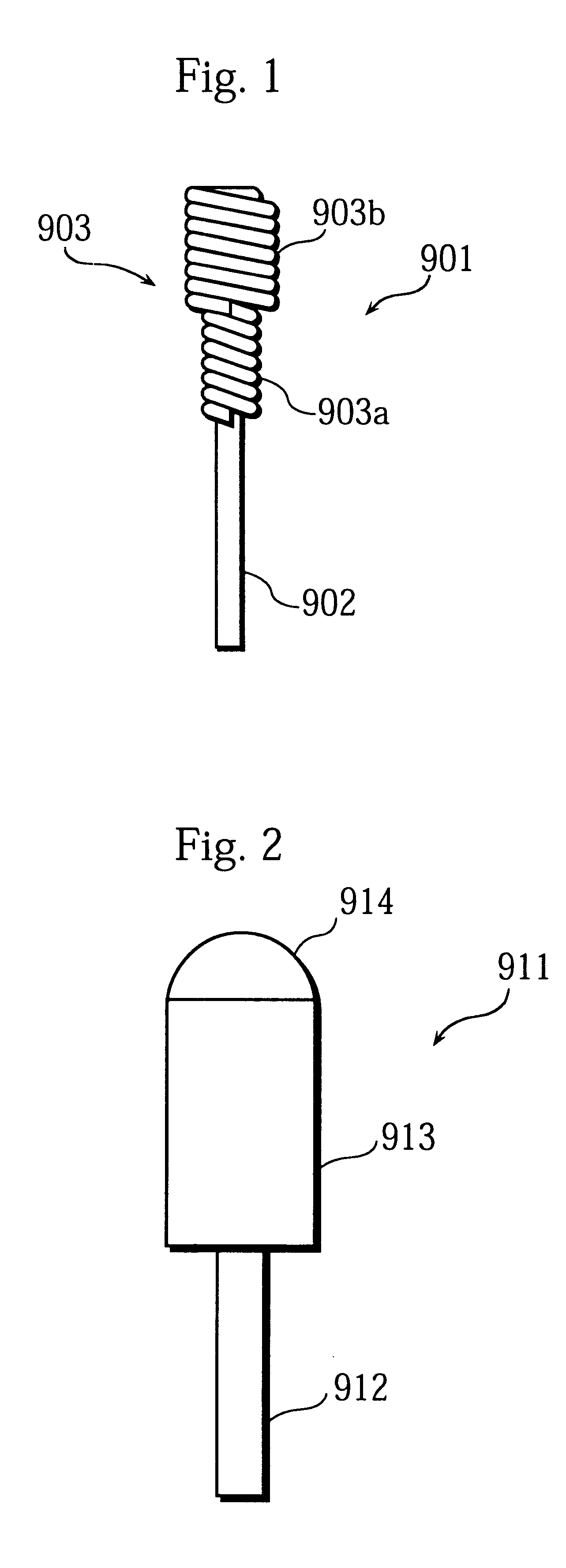
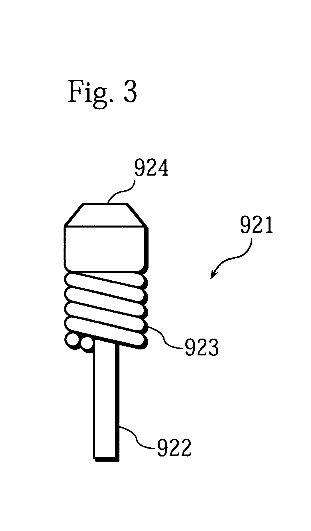
FIG. 9 is a front view showing the...

third embodiment

In the third embodiment of the present invention, an explanation is given for results obtained by studying the content of impurities contained in an electrode whose major constituent is tungsten.

In general, tungsten preferably contains less impurities, such as potassium, iron, aluminum, calcium, chromium, molybdenum, nickel, and silicon. Yet, it is difficult to completely remove these impurities from tungsten using an existing purification method. To address this problem, the inventor studied the electrode 24 that is to be used in a high pressure discharge lamp as described in the second embodiment so as to find out the level of impurity content in the electrode 24 at which blackening can be more effectively prevented.

The following is a brief explanation how blackening occurs in relation to the impurity content in the electrode. The tungsten forming the electrode 24 is easily alloyed with potassium, iron, aluminum, calcium, chromium, molybdenum, nickel, and silicon that are containe...


PUM


Abstract

A high pressure discharge lamp has a pair of electrodes in a discharge tube. Each electrode includes a coil and an electrode rod with a tip, the coil being set around the electrode rod near the tip. The tip of the electrode rod and an adjacent portion of the coil are fused together during the initial discharge. To be more specific, the coil covers the electrode rod near the tip, with the tip of the electrode rod being left uncovered and a length of the tip being DELTAL that satisfies an inequality 1/50*R3<=DELTAL<=1/5*R3 where R3 is an outer diameter of the coil adjacent to the tip. Alternatively, the electrode can be first formed before being set in the discharge tube, by integrally melting the tip of the electrode rod and the adjacent portion of the coil using, for example, a plasma or laser.

Description

(1) Field of the InventionThe present invention relates to a high pressure discharge lamp that is used in general lighting fixtures and optical instruments, and also relates to a high pressure discharge lamp electrode, a method of producing the high pressure discharge lamp electrode, and an illumination device and an image display apparatus respectively using the high pressure discharge lamps.(2) Description of Related ArtConventionally, a light source and a concave reflecting mirror are usually formed in one piece as an illumination device that is provided in an image display apparatus, such as a liquid crystal projector. As a light source of the illumination device, a high pressure mercury lamp with a short arc, which is close to a point light source, has been used. The high pressure mercury lamp has advantages, such as an excellent luminous efficiency, high intensity, favorable balance of red, blue, and green in emitted light, and long life. As one example of a high pressure disc...

Claims


Application Information

Patent Timeline
Patent Type & Authority Patents(United States)
IPC IPC(8): H01J61/06H01J61/073
CPCH01J61/073H01J61/025
Inventor TAKEUCHI, NOBUYOSHI
Owner PANASONIC CORP
Why Eureka
Try Eureka