Evaporator unit for an inhaler

a technology of evaporator unit and inhaler, which is applied in the direction of inhalators, positive displacement liquid engines, tobacco, etc., can solve the problems of entraining liquid drops and hardly controllable, and achieve the effect of poor responsiveness

Active Publication Date: 2021-06-29
KÖRBER TECH GMBH
View PDF9 Cites 0 Cited by
  • Summary
  • Abstract
  • Description
  • Claims
  • Application Information

AI Technical Summary

Benefits of technology

[0005]The invention solves this object with the features of the independent claims. According to the invention, the evaporator unit has a circulation line in which the evaporator is arranged. A circulation device is arranged in the circulation line for circulating the liquid through the circulation line. During circulation of the liquid according to the invention, a permanent mixing of the liquid to be vaporized is attained, keeping the composition of the circulated liquid substantially constant. By arranging the evaporator in the circulation line according the invention, a constant liquid composition is realized up to the area of vapor formation, and the primary goal of a constant vapor composition is also attained. Particularly to avoid big local composition gradients, forced convection of the liquid volume enclosed in the circulation line is realized according to the invention.
[0009]To avoid high thermal loads and corresponding poor responsiveness, the evaporator unit is realized as small as possible. The evaporator and / or evaporator unit are preferably made on the basis of MEMS-technology and therefore preferably as a single microelectromechanical system.

Problems solved by technology

Furthermore, a composition gradient in the wick profile can lead to hardly controllable spontaneous vaporization of liquid in the centre of the wick, leading to entraining of liquid drops.

Method used


Image

  • Evaporator unit for an inhaler
  • Evaporator unit for an inhaler
  • Evaporator unit for an inhaler

Examples


Embodiment Construction

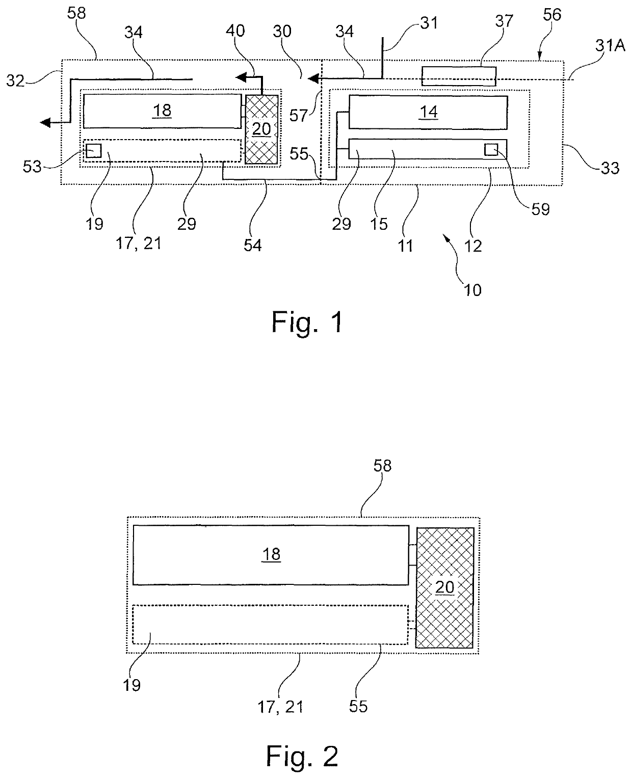
[0014]The electronic cigarette product 10 comprises a substantially rod-shaped or cylindrical housing 11. In the housing 11, an air channel 30 is provided between at least one air inlet opening 31 and the mouthpiece 32 of the cigarette product 10. The mouthpiece 32 of the cigarette product 10 is related to the end at which the consumer inhales, thereby applying vacuum to the cigarette product 10 and creating an air stream 34 in the air channel 30. At least one air inlet opening 31 can be arranged at the shell side of the housing 11. Additionally or alternatively, at least one air inlet opening 31A can be arranged at the distant end 33 of the cigarette product 10. The distant end 33 of the cigarette product 10 is referred to the end of the cigarette product 10 opposite to the mouthpiece 32.

[0015]Behind one or more air inlets 31, 31A in the flow path of the air stream 34, preferably an air heating device 37 can be arranged for heating up or pre-heating the entering air. Aerosol formin...


PUM


Abstract

Evaporator unit for an inhaler comprising an evaporator having a heating element for vaporizing a liquid fed through said evaporator. Said evaporator unit comprises a circulation line in which said evaporator is arranged. A circulation device is arranged in said circulation line for circulating the liquid through said circulation line.

Description

CROSS REFERENCE TO A RELATED APPLICATION[0001]This application claims priority under 35 U.S.C. § 119(e) of German Patent Application No. DE 10 2017 104555.4, filed Mar. 6, 2017, which is incorporated herein by reference in its entirety.FIELD OF INVENTION[0002]The present invention relates to an evaporator unit for an inhaler, with an evaporator having a heating element for vaporizing a liquid fed through the evaporator.BACKGROUND OF INVENTION[0003]During vaporizing of e-liquids in usual wick-coil-evaporators with a feeding stream of fresh liquid from the tank, inside the wick a glycerine enriched composition is settled, in which the gas phase composition coincides with that of the feeding stream liquid. This relates to a corresponding boiling temperature. In the wick, a glycerine enriched composition is settled at the edge, which is most likely not constant along the wick. It can be shown, that in this case, in partial areas of the wick higher boiling temperatures have to appear, as...

Claims


Application Information

Patent Timeline
Patent Type & Authority Patents(United States)
IPC IPC(8): A24F47/00F04B17/03F04B23/04F04B19/00F04B43/04A61M11/04A61M15/06A24F40/10A24F40/48A24F40/485
CPCF04B17/03A24F47/008A61M11/042A61M15/06F04B19/006F04B23/04F04B43/043A24F40/10A24F40/48A24F40/485
Inventor SCHMIDT, RENEKESSLER, MARC
Owner KÖRBER TECH GMBH
Why Eureka
Try Eureka