
Chipper Knife and Method of Manufacturing a Chipper Knife

a technology which is applied in the field of chipper knife and manufacturing method of chipper knife, can solve the problems of small but significant working stripes of the chipper knife parallel to the cutting edge, increased strain on the chipper knife and the rest of the chipper, and lower chip quality

Active Publication Date: 2010-07-01
IGGESUND TOOLS
View PDF2 Cites 4 Cited by
  • Summary
  • Abstract
  • Description
  • Claims
  • Application Information

AI Technical Summary

Benefits of technology

"The present invention aims to solve problems with chipper knives by providing a method of manufacturing a chipper knife with a thickened cutting edge portion next to the cutting edge on at least one of its sides. This helps to minimize reworking of the cutting edge and reduces the need for grinding or polishing. The thickened cutting edge portion can be worked to have small working stripes at an angle to the cutting edge, which act as indications of fracture and promote fatigue failure and increased friction in chipping. However, by providing a thickened cutting edge portion and reworking it to have small working stripes at an angle, the invention eliminates these drawbacks and provides advantages such as reduced interfering influence on the feeding of pieces of wood to the chipper and increased clearance for the chips. The invention also allows for the cutting edge to be positioned on either the wood side or chip side of the chipper knife, depending on the desired manufacturing process. The thickened cutting edge portion can be worked using grinding or polishing discs, or by using other techniques such as milling. Overall, the invention provides a method for manufacturing a chipper knife with a thickened cutting edge portion that reduces the need for grinding or polishing and eliminates the drawbacks associated with working the cutting edge."

Problems solved by technology

However, there arises the drawback that the chipper knife will have small but significant working stripes parallel to the cutting edge.
These working stripes function as small indications of fracture, which reduce the tensile strength to bending forces at an angle to the cutting edge, increase the risk of fatigue failure and cause increased friction in chipping which results in increased strain in both the chipper knife and the rest of the chipper, lower quality of the chips and increased consumption of power.

Method used


Image

  • Chipper Knife and Method of Manufacturing a Chipper Knife
  • Chipper Knife and Method of Manufacturing a Chipper Knife
  • Chipper Knife and Method of Manufacturing a Chipper Knife

Examples


Embodiment Construction

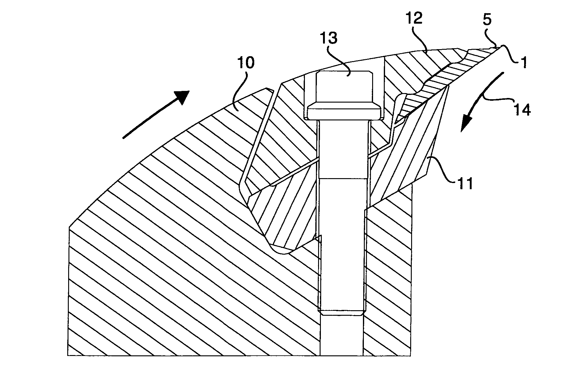
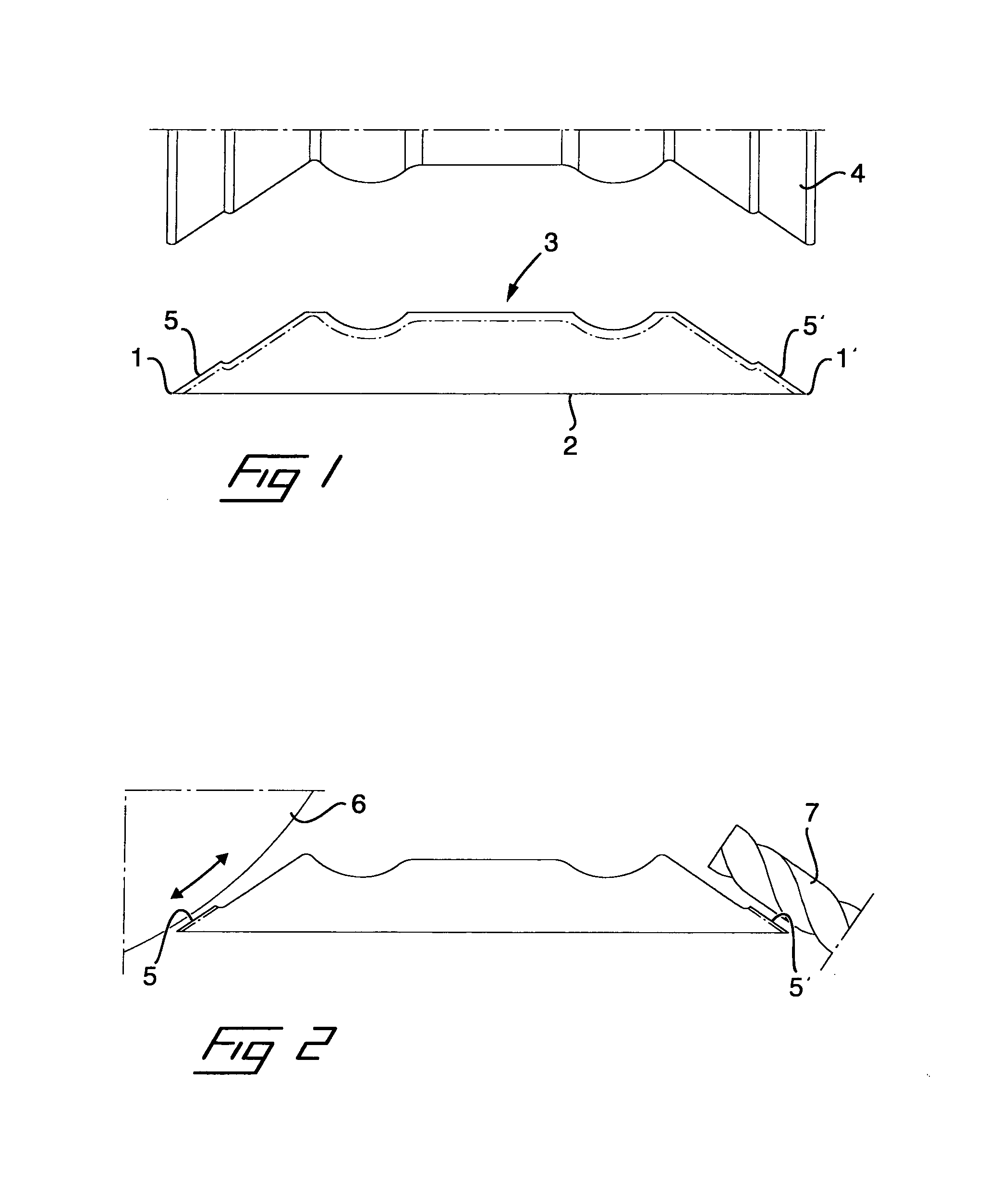
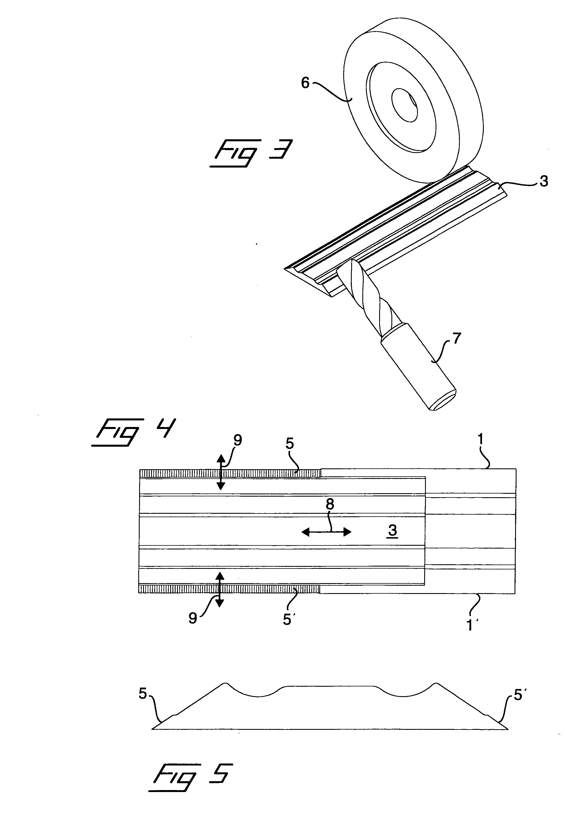
[0025]FIGS. 1-6 illustrate a chipper knife which has two cutting edges 1, 1′. The chipper knife has a completely flat underside 2 while an upper side 3, which is adapted to be oriented toward a wood side, has a profiled shape in cross-section. The respective cutting edges 1, 1′ are formed between the underside 2 and a bevelled surface on the upper side.

[0026]FIG. 1 illustrates a blank for the chipper knife, which can be made, for example, by rolling, and which has a certain oversize relative to the shape of the completed chipper knife as indicated by a dash-dotted line. The final shape of the upper side is obtained, in the shown embodiment, by deep feed grinding by means of a rotating grinding wheel 4 which rotates in a plane parallel to the longitudinal extent of the clipper knife and which has a profiled shape that conforms with the desired shape of the upper side of the chipper knife. In grinding, the chipper knife will obtain shallow but characteristic working stripes in its lon...


PUM

PropertyMeasurementUnit
angleaaaaaaaaaa
angleaaaaaaaaaa
thicknessaaaaaaaaaa

Abstract

The invention relates to a chipper knife of the type that is adapted to be mounted in chippers which have a rotatable tool, in the form of a disc, drum or frustoconical member, on which are mounted a plurality of such chipper knives to provide, during rotation of the tool and simultaneous feeding of pieces of wood to the same, material-cutting working or disintegrating of the pieces of wood into chips by means of at least one cutting edge (1, 1′). At least a first side of the chipper knife has a raw, unworked surface or working stripes in the longitudinal direction of the chipper knife, that is substantially parallel to the cutting edge. This first side also has a thickened cutting edge portion (5, 5′) in the area next to the cutting edge, which edge portion has working stripes in the transverse direction of the chipper knife, at an angle to the cutting edge. The invention also relates to a method of manufacturing such a chipper knife.

Description

[0001]The present invention relates to a chipper knife of the type that is adapted to be mounted in chippers which have a rotatable tool, in the form of a disc, drum or frustoconical member, on which are mounted a plurality of such chipper knives to provide, during rotation of the tool and simultaneous feeding of pieces of wood or timber to the same, material cutting working or disintegrating of the pieces of wood into chips, comprising at least one cutting edge which is defined between two edge forming surfaces at an acute angle to each other, at least a first side of the chipper knife having a raw, unworked surface or working stripes in the longitudinal direction of the chipper knife, that is substantially parallel to the cutting edge.[0002]The invention also concerns a method of manufacturing such a chipper knife.BACKGROUND ART[0003]Chipper knives of the above type are in operation subjected to very great forces. Since it is advantageous for economical reasons if each chipper kni...

Claims


Application Information

Patent Timeline
Patent Type & Authority Applications(United States)
IPC IPC(8): B27L11/00B02C18/18B23P15/28B24B1/00
CPCB23P15/40B27L11/005
Inventor ANDERSSON, TORBJORNBACKLUND, TORBJORN
Owner IGGESUND TOOLS
Learn More