Wave generating system for converting ocean waves into usable energy

a technology of wave generating system and energy conversion technology, which is applied in the direction of electric generator control, machines/engines, mechanical equipment, etc., can solve the problems of insufficient energy displacement of carbon-based fuel as the primary source of energy for much of the world, cost-competitive with most carbon-based fuels, and marginalization of renewable energy sources, so as to achieve low cost, low environmental impact, and low cost of energy supply

Inactive Publication Date: 2010-07-01
LAWSON JOHN
View PDF5 Cites 9 Cited by
  • Summary
  • Abstract
  • Description
  • Claims
  • Application Information

AI Technical Summary

Benefits of technology

[0010]It is an object of the present invention to provide a system for the purpose of supplying inexpensive energy to various cargo distribution industries. The present invention can be used in conjunction with a transportation system capable of moving containerized cargo many miles inland. The resulting transportation system would impart minimal or no carbon-based emissions with minimum impact to environment.

Problems solved by technology

Although many of these renewable sources of energy show great promise and potential, they have hitherto been insufficient at displacing carbon-based fuels as the primary source of energy for much of the world.
One of the most fundamental deficiencies with most renewable sources of energy is the fact that they are not cost-competitive with most carbon-based fuels.
As such, renewable sources of energy will continue to be marginalized until their cost effectiveness increases relative to the cost of carbon-based fuels.
In other words, it is not possible to harness enough energy at night time or during days with overcast weather.
Moreover, a closely related dilemma is the fact that power provided to the electrical grid must be used instantly and is typically not stored.
And issue compounding the problem is the fact transmission loss due to line resistance will only further lessen the yield of energy output from many renewable “green sources” of energy.
By way of example, electrical transmission through power lines results in a substantial loss of energy through the mere distribution of transferring that energy from one point to another.

Method used


Image

  • Wave generating system for converting ocean waves into usable energy
  • Wave generating system for converting ocean waves into usable energy
  • Wave generating system for converting ocean waves into usable energy

Examples


Embodiment Construction

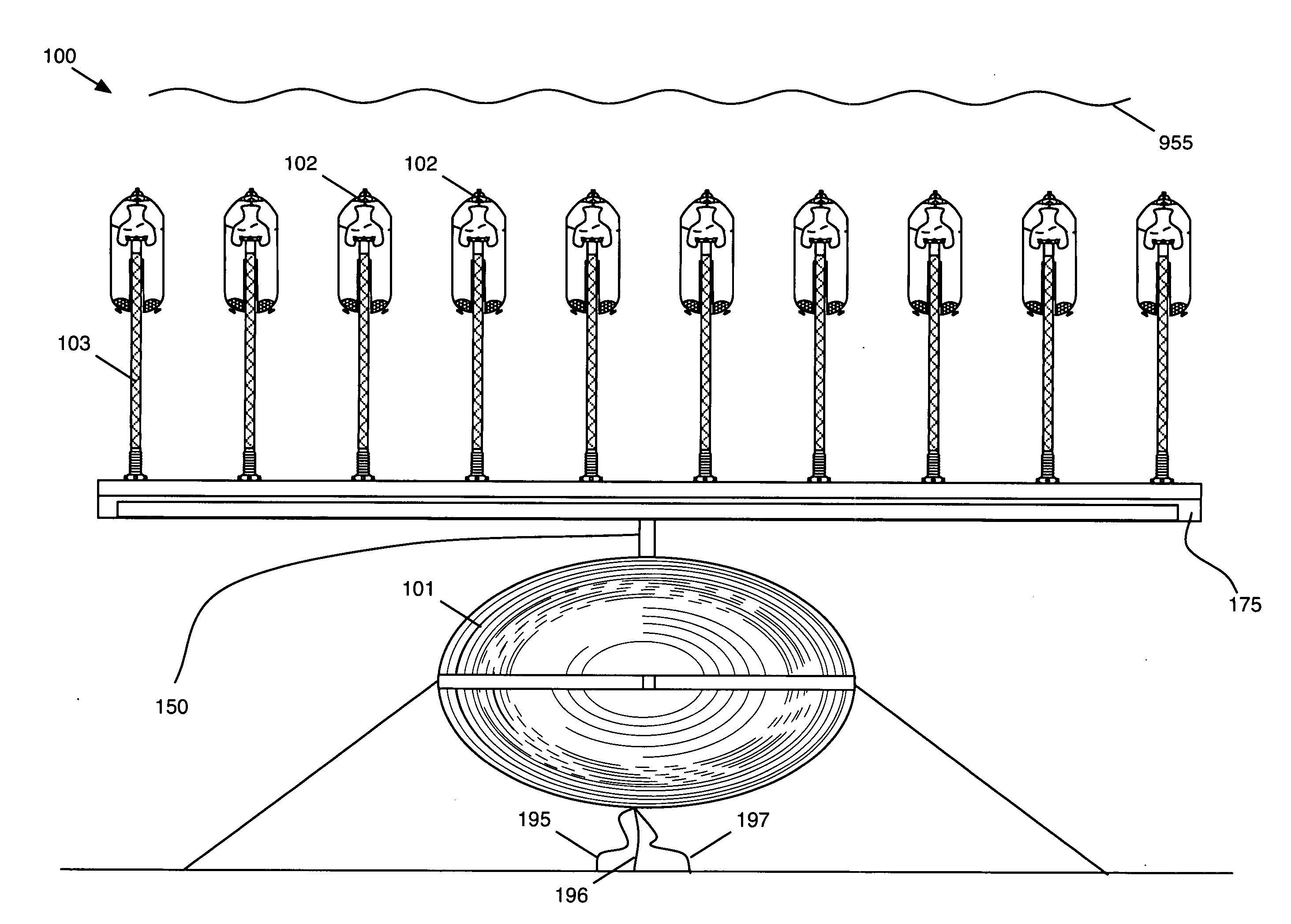
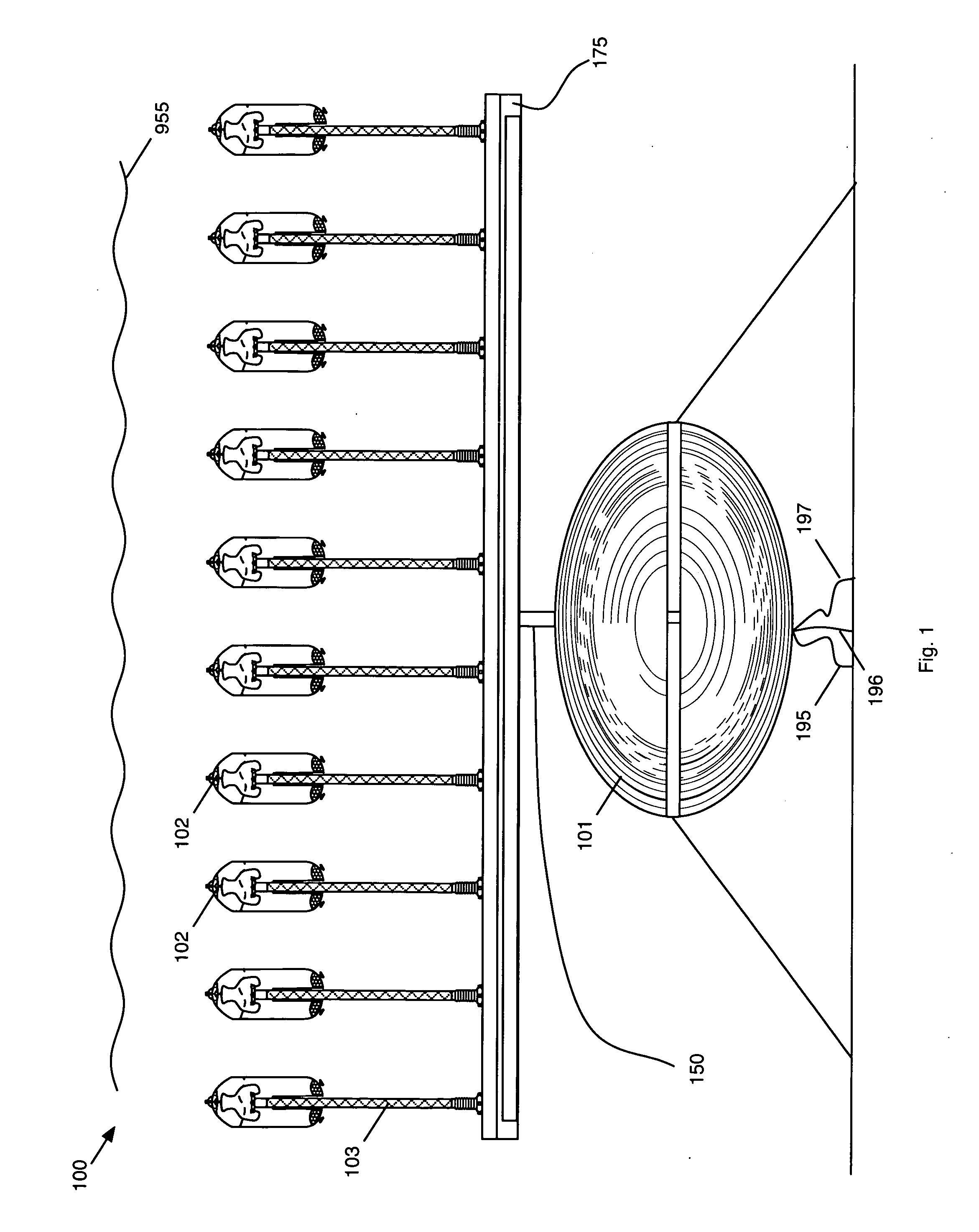
[0023]According to a preferred embodiment of the present invention, a unique system is employed to use wave motion from swells in oceans or seas to generate Oxygen and Hydrogen through the process of electrolysis. The present invention is described in enabling detail below.

[0024]FIG. 1 illustrates a preferred embodiment of the present invention. A Wave Generating System for Converting Ocean Waves into Usable Energy 100 includes a Base 101, a Polyp 102, and a Stem 103. The Polyp 102 is held in position by a large diameter flexible air hose called a Stem 103. The Stem 103 is connected to the Base 101. The Stem 103 prevents drift and supplies the Polyps 102 with air to make buoyancy adjustments. Air is bled from the Base 101 through the Stem 103 and into the buoyancy compensation device when necessary.

[0025]In some preferred embodiments the Base 101 may require a mooring design to counter both the upward force and a tendency to tip, which can release gas. The Stem 103 secures the Polyp...


PUM


Abstract

A Wave Generating System for Converting Ocean Waves into Usable Energy includes a Base, a Polyp, and a Stem. The Polyp is connected to the Stem. The Stem is connected to the Base. In some preferred embodiments the Base may require a mooring design to counter both the upward force and a tendency to tip, which can release gas.The Base is comprised of a plurality of first chamber, a second chamber, and a third chamber. In some preferred embodiments, the first chamber may be used to store Hydrogen, the second chamber may be used to store Oxygen, and the third chamber may be used to store breathable air for operators. The third chamber is also used for the purpose of imparting buoyancy to the Base.

Description

FIELD OF THE INVENTION [0001]The present invention is in the area of renewable energy systems.BACKGROUND OF THE INVENTION [0002]Many renewable sources of energy currently in development have been prompted by concerns over the rapidly decreasing reserves of oil, carbon emissions, and the volatile price fluctuations of various energy commodities. Although many of these renewable sources of energy show great promise and potential, they have hitherto been insufficient at displacing carbon-based fuels as the primary source of energy for much of the world.[0003]One of the most fundamental deficiencies with most renewable sources of energy is the fact that they are not cost-competitive with most carbon-based fuels. As such, renewable sources of energy will continue to be marginalized until their cost effectiveness increases relative to the cost of carbon-based fuels.[0004]For instance, with respect to solar energy, the efficacy of solar power is circumscribed by the amount of sunshine avai...

Claims


Application Information

Patent Timeline
Patent Type & Authority Applications(United States)
IPC IPC(8): F03B13/18
CPCF03B13/1855F05B2240/97Y02E10/38Y02E10/30
Inventor LAWSON, JOHN
Owner LAWSON JOHN
Why Eureka
Try Eureka