Circuit arrangement and method for operating at least one LED and at least one fluorescent lamp

a technology of led and fluorescent lamps, applied in the direction of lighting apparatus, electroluminescent light sources, light sources, etc., can solve the problems of reliably preventing undesirable switching combinations, limiting the entire subcircuit required for the operation of leds, etc., and achieves the effect of preventing current flow, and reducing the number of leds

Inactive Publication Date: 2010-07-01
OSRAM GMBH
View PDF5 Cites 19 Cited by
  • Summary
  • Abstract
  • Description
  • Claims
  • Application Information

AI Technical Summary

Benefits of technology

[0019]It is furthermore preferred that a resistive voltage divider is coupled between the two output terminals of the timer, the tap of said voltage divider being coupled to the control electrode of the LED switch. Said voltage divider serves for quasi artificially increasing the potential between control and reference electrodes of the LED switch. In a development of this embodiment, it can be provided that the part of the voltage divider which is coupled between the first output terminal of the timer and the control electrode of the LED switch includes a second diode which is oriented in such a way that it prevents a current flow from the control electrode of the LED switch to the output of the timer. What is thereby achieved is that the depletion of the control electrode of the LED switch is solely realized only by the resistor between control electrode and reference electrode of the LED switch or respectively second output terminal of the timer (that is to say by the lower part of said voltage divider), which is advantageous for the tolerance behavior of the circuit. Furthermore, the switch-off of the LED switch is accelerated because, in particular, the reaction of the LED switch driving to falls in the voltages at the inputs of the timer is digitized. Both lead to a reliable and rapid switch-off of the LED switch which is correspondingly required by the timer.
[0020]It has proved to be advantageous if a circuit arrangement according to the invention furthermore includes an electrical coupling between the operating electrode of the LED switch and the first output terminal of the timer, which electrical coupling is embodied in such a way that it brings about current negative feedback of the LED switch. This achieves the advantage that the LED switch never attains deep saturation and, as a result, turns off somewhat more rapidly and primarily more reliably since this process has now become independent of the storage time of the LED switch. Although the turn-off itself does not become “sharper”, tolerance-dependent time delays are none the less minimized.
[0021]A further preferred embodiment is distinguished by the fact that the operating electrode of the LED switch is coupled to the first output terminal of the timer via a third diode which is oriented in such a way that it acts as an antisaturation diode for the LED switch. This ensures that the LED switch turns off even more rapidly, that is to say that the small disadvantage associated with the current negative feedback is resolved as well, and the fluorescent lamp comes on even more reliably in return. It thus serves for stabilizing the charge lead of the starting capacitor.

Problems solved by technology

As a result of the coupling to the starting circuit, the entire subcircuit required for the operation of the LEDs is reliably limited to the triggering voltage of the starting device.
This means that undesirable switching combinations are reliably precluded.

Method used


Image

  • Circuit arrangement and method for operating at least one LED and at least one fluorescent lamp
  • Circuit arrangement and method for operating at least one LED and at least one fluorescent lamp
  • Circuit arrangement and method for operating at least one LED and at least one fluorescent lamp

Examples


Embodiment Construction

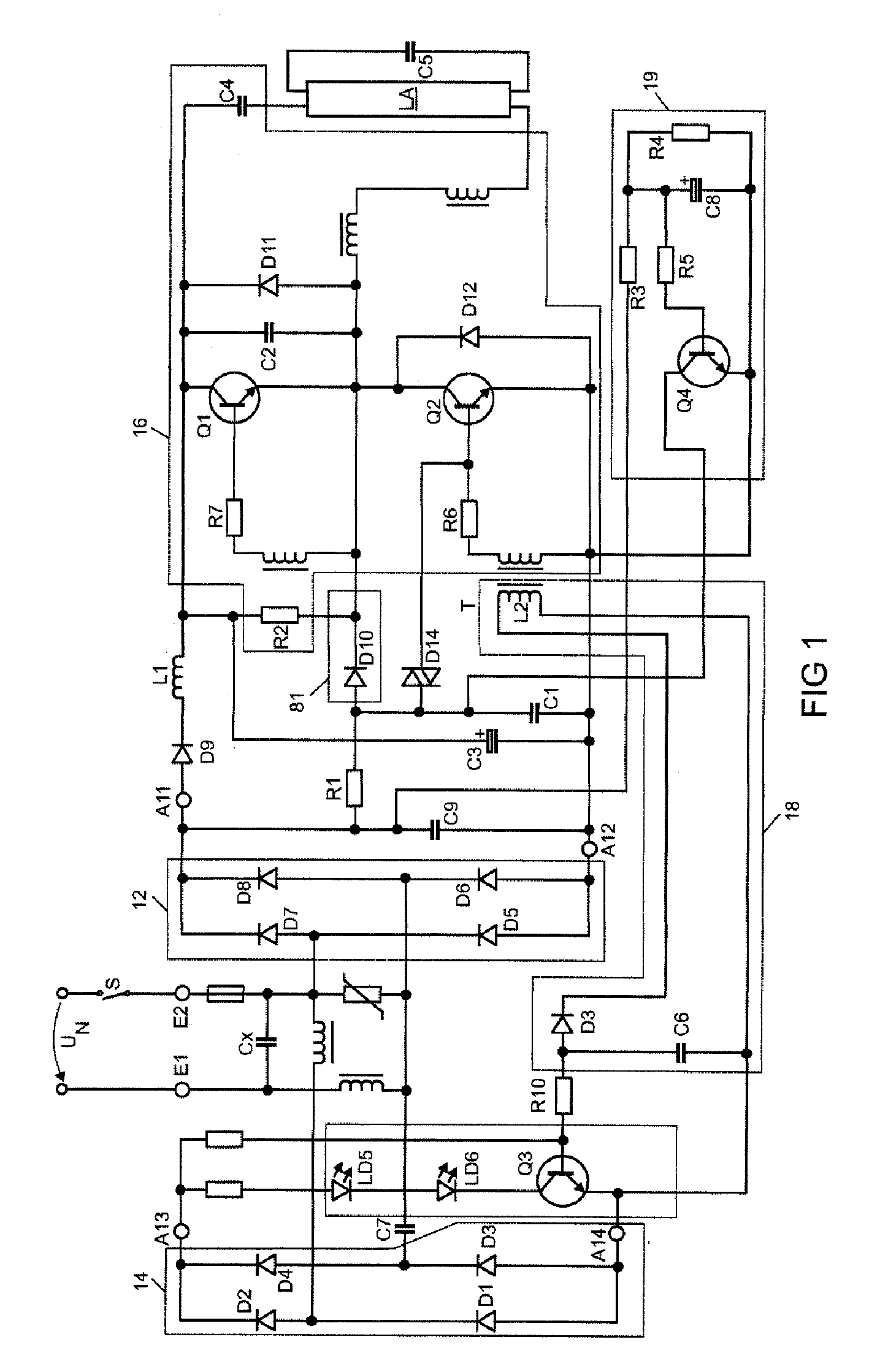
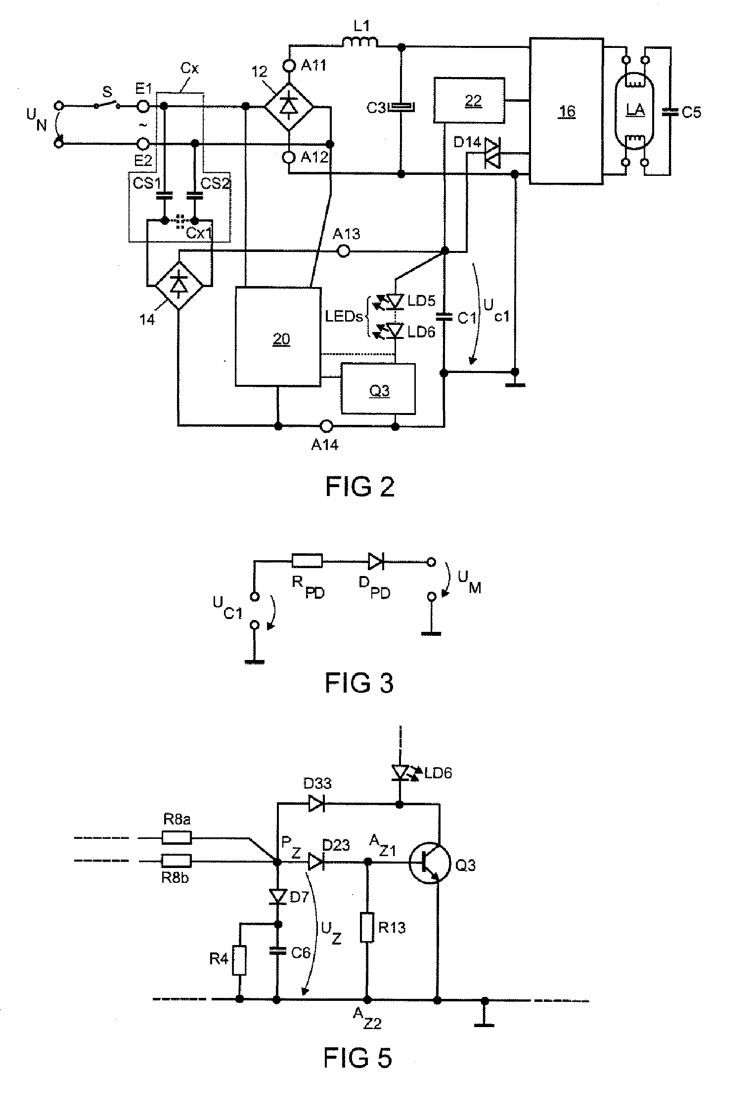
[0035]The reference symbols that have already been introduced with reference to FIG. 1 will continue to be used below for identical or functionally identical components. They will not be introduced again, for the sake of clarity.

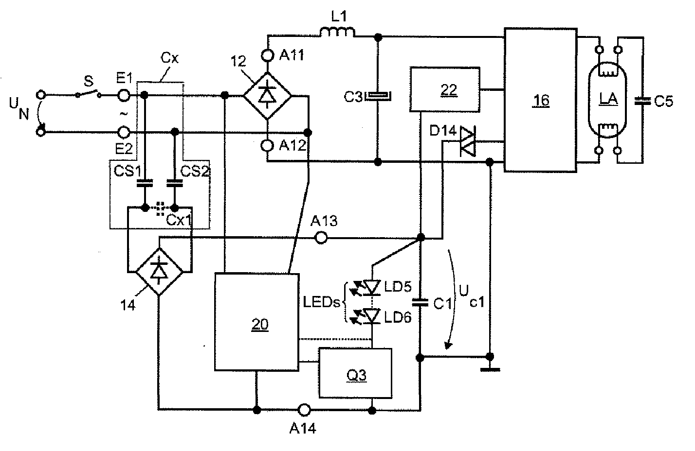
[0036]FIG. 2 shows in schematic illustration the construction of a circuit arrangement according to the invention. The input terminals E1, E2 can be coupled to an AC supply voltage UN representing the power supply system voltage, in particular, via a switch S. In this case, the input terminals E1 and E2 are coupled to a main rectifier 12. Moreover, the input terminal E1 is coupled to the first input terminal of an auxiliary rectifier 14 via a capacitor CS1 and the second input terminal E2 is coupled to the second input terminal of the auxiliary rectifier 14 via a second capacitor CS2. Moreover, an X-capacitance CX1 is coupled between the two inputs of the auxiliary rectifier. The combination of the capacitors CS1, SS2 and CX1 corresponds to the capacitor CX ...


PUM


Abstract

A circuit arrangement for operating an LED and an fluorescent lamp may include a main rectifier; an auxiliary rectifier; an inverter, the output of said inverter having a terminal for connecting the fluorescent lamp; a starting device, wherein its first terminal is coupled to a control electrode of one of the switches of the inverter; a pull-down circuit; and a starting capacitor; wherein the second terminal of the starting device and the second terminal of the pull-down circuit are coupled to the first output terminal of the auxiliary rectifier; wherein the starting capacitor is coupled between the first and the second output terminal of the auxiliary rectifier; and wherein there is arranged in parallel with the starting capacitor a series circuit including a first and a second terminal for the LED and an LED switch, wherein the LED switch has a control electrode, an operating electrode and a reference electrode.

Description

TECHNICAL FIELD [0001]The present invention relates to a circuit arrangement for operating at least one LED and at least one fluorescent lamp including an input having a first and a second input terminal for connecting an AC supply voltage; a main rectifier having a first and a second input terminal and a first and a second output terminal, wherein the first and the second input terminal of the main rectifier are coupled to the first and the second input terminal for connecting the AC supply voltage, an auxiliary rectifier having a first and a second input terminal and a first and a second output terminal wherein the first and the second input terminal of the auxiliary rectifier are coupled to the first and the second input terminal for connecting the AC supply voltage, an inverter including at least one series circuit formed by a first and a second switch wherein the series circuit is coupled to the first and the second output terminal of the main rectifier, and the output of the i...

Claims


Application Information

Patent Timeline
Patent Type & Authority Applications(United States)
IPC IPC(8): H05B37/02
CPCH05B33/0803H05B33/0845H05B35/00H05B37/0245H05B41/36H05B45/00H05B47/175H05B45/30Y02B20/30
Inventor DELLIAN, HARALDFRANCK, FELIX
Owner OSRAM GMBH
Why Eureka
Try Eureka