Current regulator

a current regulator and current technology, applied in the direction of electric variable regulation, process and machine control, instruments, etc., can solve the problems of many “bottlenecks” occurring, the current of the two input sources cannot be balanced, and the application limit is limited

Active Publication Date: 2010-07-01
ASUSTEK COMPUTER INC +1
View PDF11 Cites 34 Cited by
  • Summary
  • Abstract
  • Description
  • Claims
  • Application Information

AI Technical Summary

Benefits of technology

[0008]The invention provides a current regulator. The current regulator includes a first switch, a second switch, a first current detecting circuit, a second current detecting circuit and a control circuit. The second end of the first switch provides a power output. The second end of the second switch is coupled to the power output. The input end of the first current detecting circuit is coupled to a first power supply, and the output end is coupled to the first end of the first switch for detecting a first current and generating a first detecting signal. The input end of the second current detecting circuit is coupled to a second power supply, and the output end is coupled to the first end of the second switch for detecting a second current to generate a second detecting signal. The control circuit receives and compares the first detecting signal and the second detecting signal to control the first switch and the second switch to be turned on or turned off.

Problems solved by technology

However, the method cannot ensure the current of the two input sources in balance.
According to current limitation stipulated in the USB and POE, the USB interface can only provide a current of 0.5 A, and the POE mode of Ethernet can provide a voltage of 48V and the maximum current of 0.35 A. However, a problem will occur when load is provided for a user side by combining the two voltages.
Apparently, it may be limited in application when the current is not balanceable.
Many “bottlenecks” occur because the current is not balanceable.

Method used


Image

  • Current regulator
  • Current regulator
  • Current regulator

Examples


Embodiment Construction

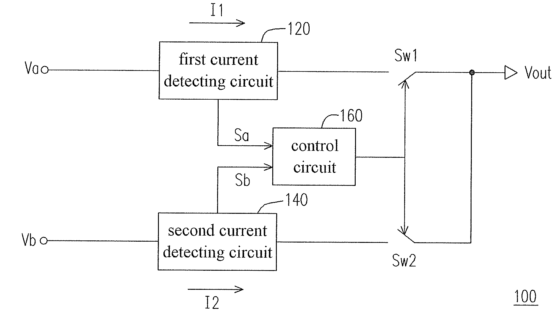
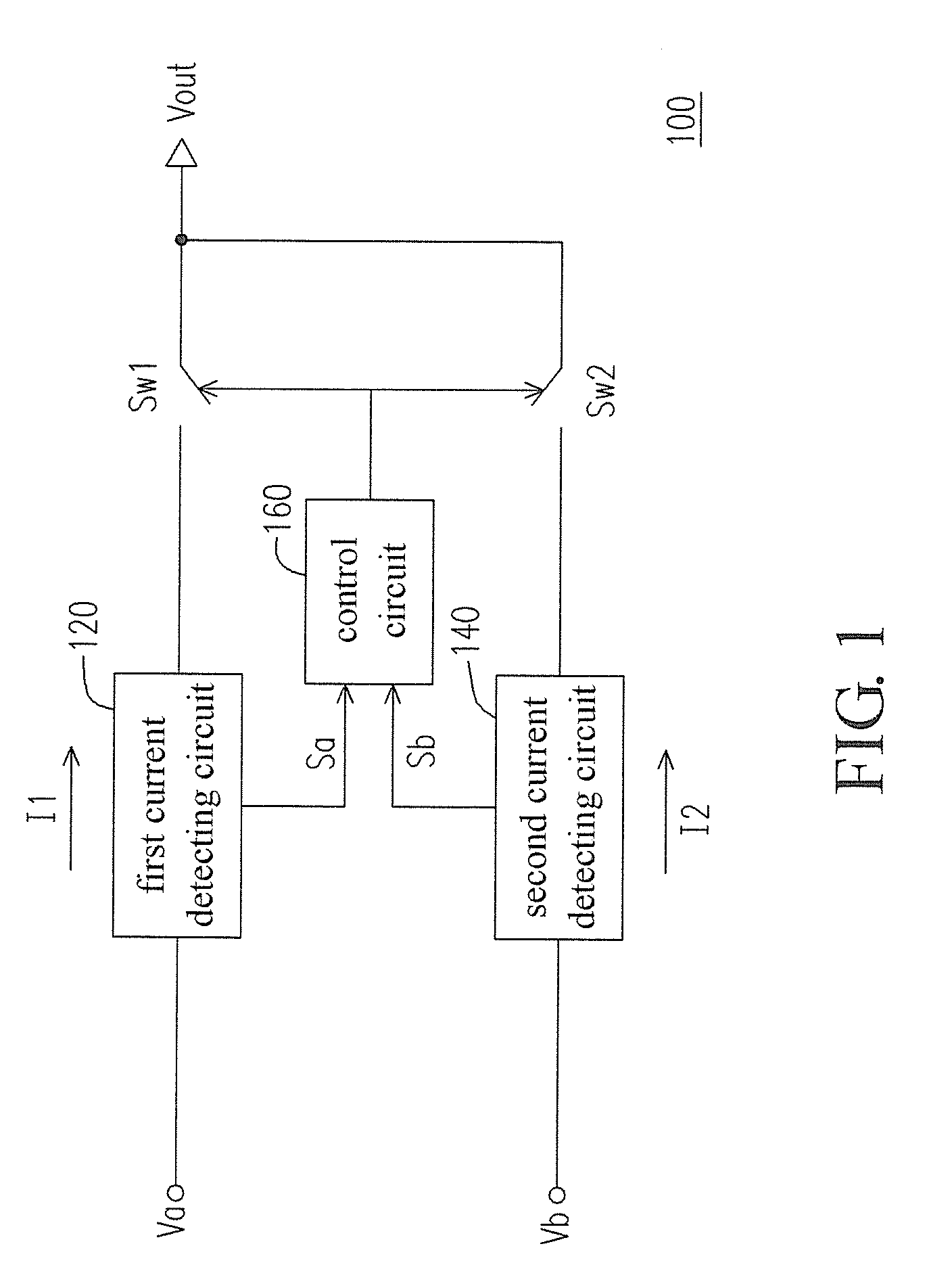
[0016]FIG. 1 is a circuit block diagram of the current regulator in an embodiment of the invention. The current regulator 100 includes a switch Sw1, a switch Sw2, a first current detecting circuit 120, a second current detecting circuit 140 and a control circuit 160.

[0017]The input end of the first current detecting circuit 120 is coupled to a first power supply Va, and the output end is coupled to the first end of the switch Sw1. The input end of the second current detecting circuit 140 is coupled to a second power supply Vb, and the output end is coupled to the first end of the switch Sw2. The control circuit 160 is coupled to the first current detecting circuit 120 and the second current detecting circuit 140. The second end of the switch Sw1 is coupled to the second end of the switch Sw2, and a power output Vout is provided from the junction of the two switches. The first power supply Va and the second power supply Vb can be two USB interface power supplies or two POE power supp...


PUM


Abstract

A current regulator includes a first switch, a second switch, a first current detecting circuit, a second current detecting circuit and a control circuit. Both of the first and second current detecting circuits detect the current of corresponding power route. The control circuit controls the first and the second switches on the route to be turned on or turned off according to detecting signals, and regulates to keep the wiring current in balance.

Description

CROSS-REFERENCE TO RELATED APPLICATION[0001]This application claims the priority benefit of Taiwan application serial no. 97151847, filed on Dec. 31, 2008. The entirety of the above-mentioned patent application is hereby incorporated by reference herein and made a part of specification.BACKGROUND OF THE INVENTION[0002]1. Field of the Invention[0003]The invention relates to a power supply device and, more particularly, to a current regulator with two power supplies.[0004]2. Description of the Related Art[0005]Generally, peripherals are powered via universal serial bus (USB) interfaces or the power over Ethernet (POE) technology.[0006]According to the standard, the USB interface can provide the maximum power 2.5 W, and the general POE can provide the maximum power 15 W. If the wattage consumed by the product is larger than the maximum wattage provided, a “bottleneck” will appear in product design. To provide the product with larger input wattage, design engineers usually connect two U...

Claims


Application Information

Patent Timeline
Patent Type & Authority Applications(United States)
IPC IPC(8): G05F1/00
CPCG05F1/56H02J1/10H04L12/10Y10T307/707
Inventor RUAN, FAI-RUEIHUANG, NUNG-TEHSU, CHIH-WAN
Owner ASUSTEK COMPUTER INC
Why Eureka
Try Eureka