

Touch Panel Structure
a touch panel and structure technology, applied in the field of thin-type displays, can solve the problems of increasing production costs, affecting the quality of products, and affecting the quality of products, and achieve the effect of high touch sensing sensitivity and reliability
- Summary
- Abstract
- Description
- Claims
- Application Information
AI Technical Summary
Benefits of technology
Problems solved by technology
Method used
Image

Examples
first embodiment
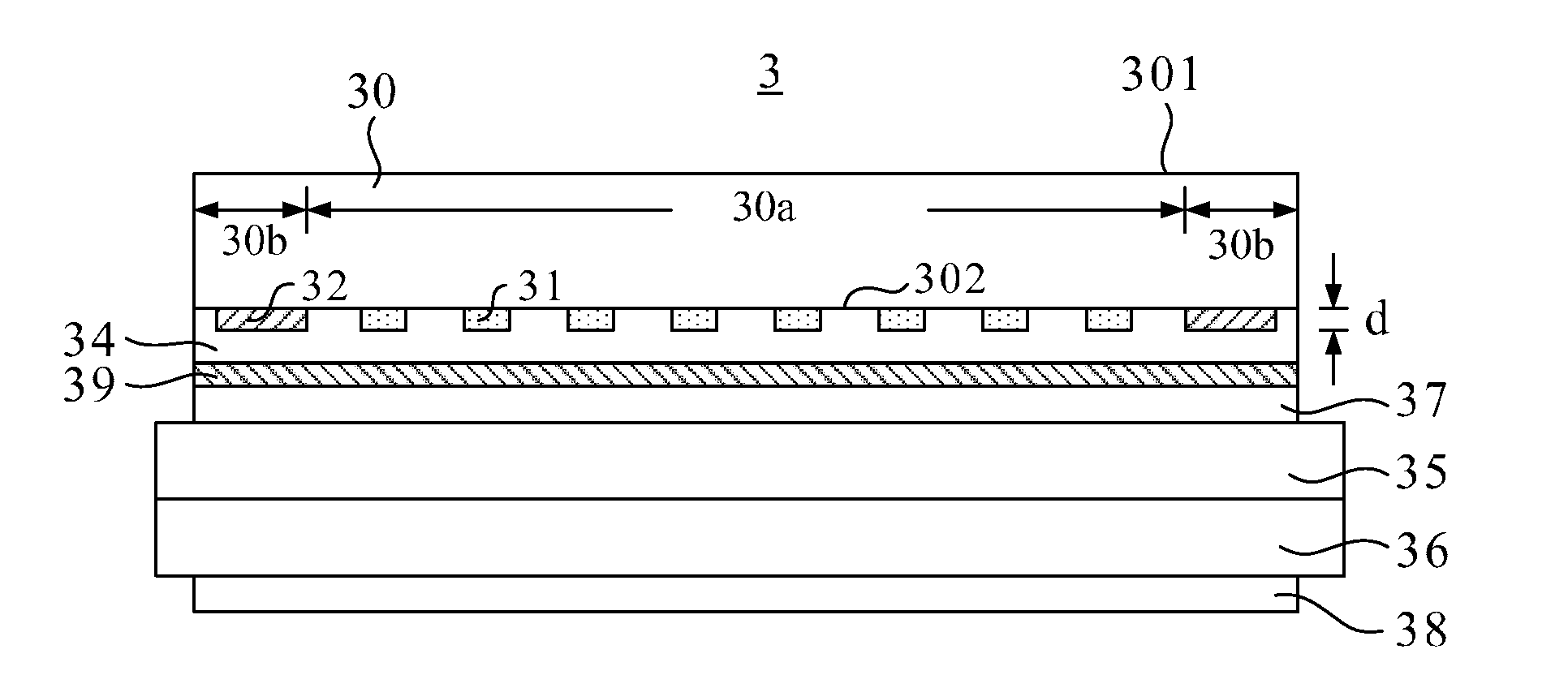
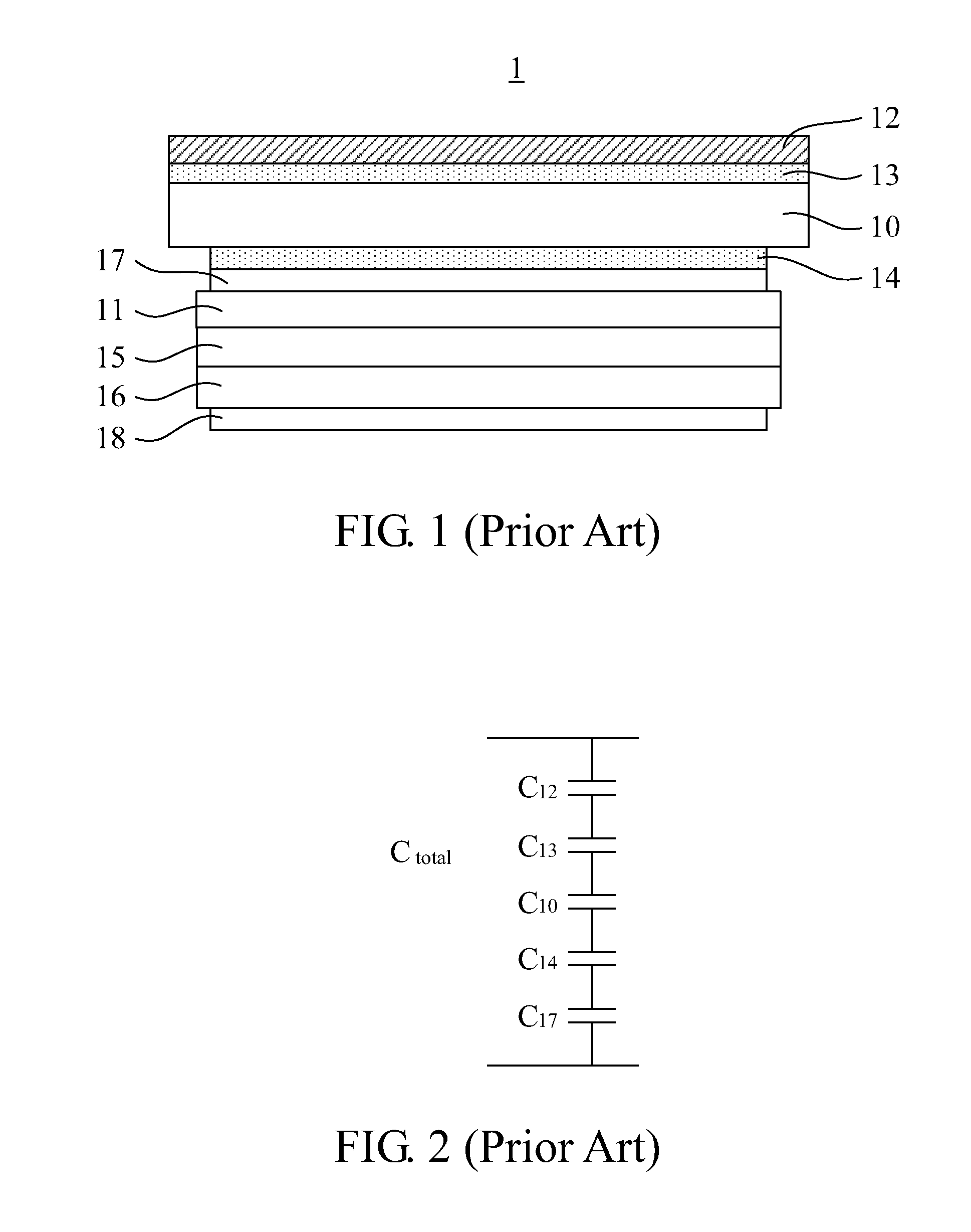
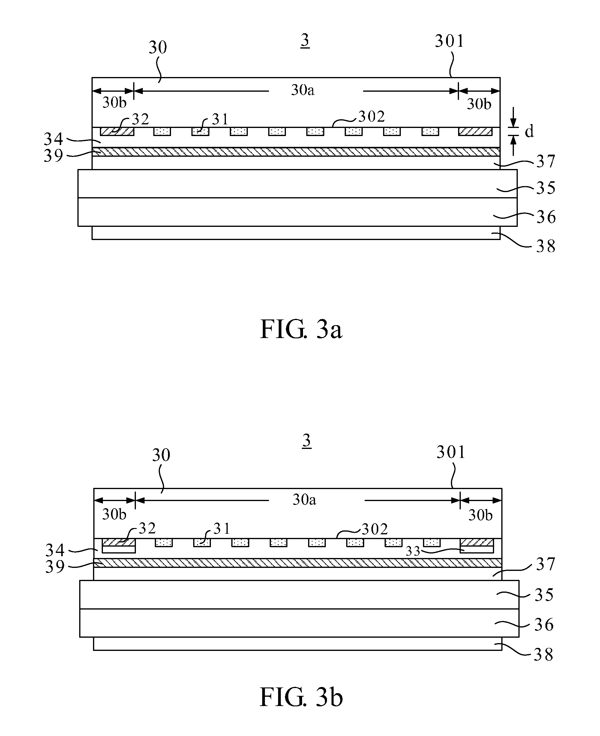
[0026]In reference to FIG. 3a, a schematic view of a touch panel structure 3 according to this invention is depicted therein. The touch panel structure 3 comprises a cover glass 30 and a touch sensing layer. In this embodiment, the touch sensing layer comprises a first transparent electrode 31, a light shielding element 32 and an adhesive protecting layer 34. The cover glass 30 has a touch surface 301 and a sensing surface 302 on two sides thereof respectively. The touch surface 301 is disposed on the outermost side of the display device for the user to touch directly. The sensing surface 302 is an inner surface opposite the touch surface 301. Additionally, in terms of the touch or display function, the sensing surface 302 of the cover glass 30 may further have a center area 30a and a peripheral area 30b defined thereon. The center area 30a corresponds to the display area of the touch panel, while the peripheral area 30b corresponds to the non-display area of the touch panel and is ...
second embodiment
[0032]FIG. 3b depicts a touch panel structure 3 according to this invention. The touch panel structure 3 of this embodiment further comprises a second transparent electrode 33 which may be used for the circuit layout at the periphery of the touch panel. The second transparent electrode 33 is disposed on the cover glass at the side of the sensing surface 302 and is located inside the peripheral area 30b. Furthermore, the second transparent electrode 33 comes into contact with the light shielding element 32 to sandwich the light shielding element 32 between the cover glass 30 and the second transparent electrode 33. In this embodiment, the second transparent electrode 33 covers the surface of the light shielding element 32 completely, although this invention is not limited thereto; i.e., the second transparent electrode 33 may also partially cover the surface of the light shielding element 32.
[0033]Similar to the first transparent electrode 31, the second transparent electrode 33 may ...
third embodiment
[0034]FIG. 4 depicts a touch panel structure 4 according to this invention. The touch panel structure 4 of this embodiment further comprises a groove 303. The groove 303 is disposed on the cover glass 30 at the side of the sensing surface 302 and located inside the peripheral area 30b; i.e., the sensing surface 302 is a surface with concave features. The groove 303 has a depth h ranging between 5 μm and 15 μm, and has a cross-section which may be a triangle, a right triangle, a square or a rectangle. The groove may be a closed groove entirely located inside the peripheral area 30b, or an open groove partially communicates with the outside and partially located inside the peripheral area 30b. The aforesaid materials of which the light shielding element 32 is made (e.g., the high-temperature endurable ceramic pigment) fills in at least the groove 303 and has a thickness d ranging between 6 μm and 17 μm.
[0035]In this embodiment, the adhesive protecting layer 34 is disposed on the cover...
PUM
 Abstract
Description
Claims
Application Information