Backlight module capable of increasing light output efficiency

a backlight module and light output technology, applied in the field of backlight modules, can solve the problems of difficult to achieve the objective, the light output efficiency of the backlight module is worse, etc., and achieve the effect of increasing the light output efficiency of the backlight module, improving alignment, and reducing optical energy loss

Inactive Publication Date: 2010-07-01
INNOLUX CORP
View PDF0 Cites 7 Cited by
  • Summary
  • Abstract
  • Description
  • Claims
  • Application Information

AI Technical Summary

Benefits of technology

[0011]A primary objective of the present invention is to provide a backlight module capable of increasing light output efficiency so as to decrease optical energy loss in the backlight module.
[0012]Another objective of the present invention is to provide a backlight module capable of increasing light output efficiency, and the backlight module improves an alignment when a light emitting element of the backlight module and a light guide plate of the backlight module are assembled together.
[0014]The present invention is capable of decreasing the optical energy loss between the light emitting element and the light guide plate, and therefore the objective of increasing the light output efficiency of the backlight module is achieved. In addition, the alignment can be improved when the light emitting element and the light guide plate are assembled together.

Problems solved by technology

This makes the light output efficiency of the backlight module 10 worse.
However, the objective is difficult to achieve.

Method used


Image

  • Backlight module capable of increasing light output efficiency
  • Backlight module capable of increasing light output efficiency
  • Backlight module capable of increasing light output efficiency

Examples


Embodiment Construction

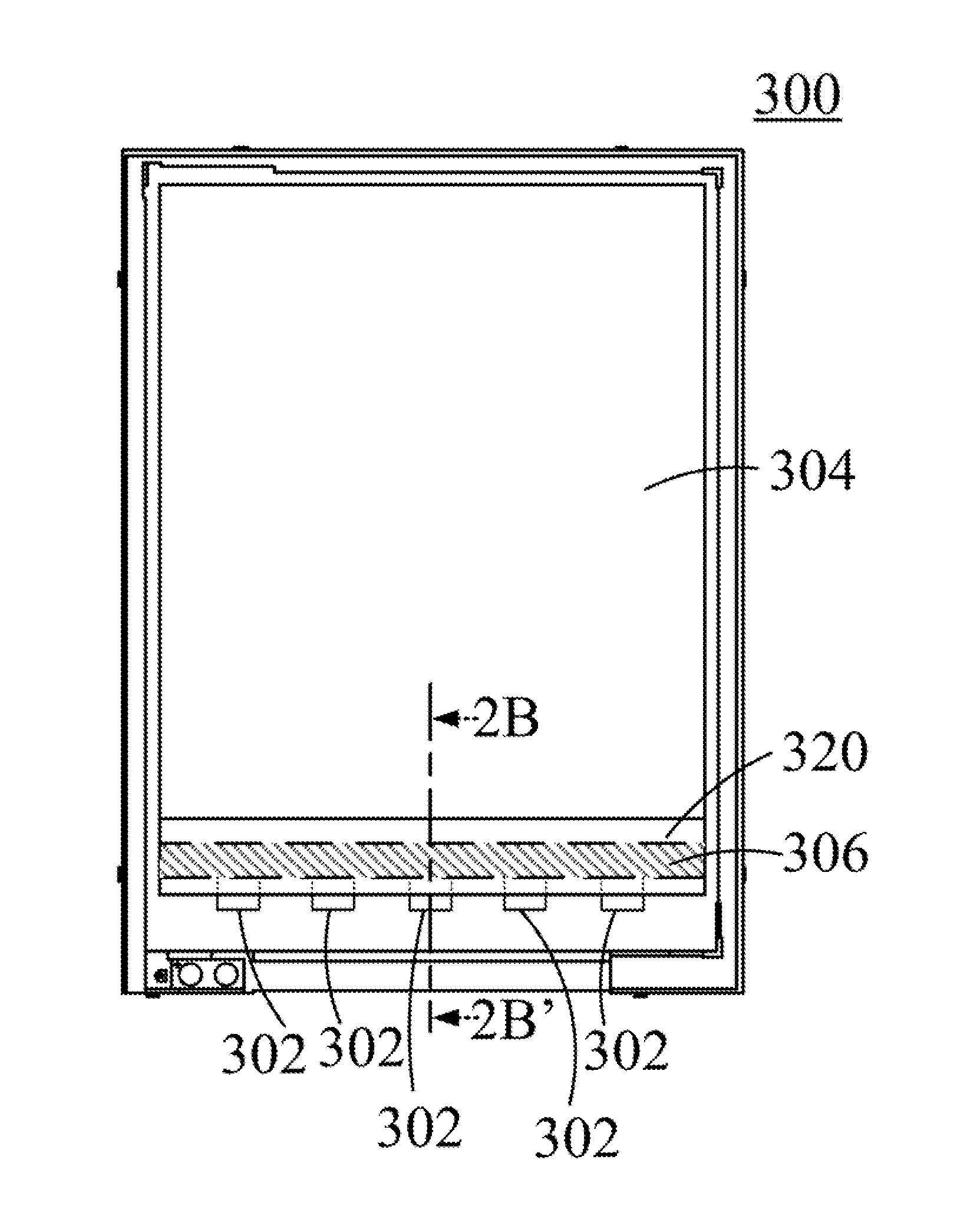
[0020]Please refer to FIG. 2A and FIG. 2B. FIG. 2A illustrates a top view of a backlight module 300 according to a preferred embodiment of the present invention. FIG. 2B illustrates a cross-sectional view along a line 2B-2B′ in FIG. 2A. The backlight module 300 mainly comprises light emitting elements 302, a light guide plate 304, an intermediate layer 306, and a flexible printed circuit board 320. The light emitting elements 302 can be light sources generally used in the backlight module 300, for example, light emitting diodes, lamps, or other usable light sources. The light guide plate 304 is disposed at a side of the light emitting elements 302 to receive lights emitted by the light emitting elements 302. The flexible printed circuit board 320 adheres to the tops of the both the light emitting elements 302 and the light guide plate 304 by using a tape 322. The flexible printed circuit board 320 provides circuit arrangements of the backlight module 300 for transmitting and control...


PUM

PropertyMeasurementUnit
refractive indexaaaaaaaaaa
light transmittanceaaaaaaaaaa

Abstract

A backlight module capable of increasing light output efficiency is disclosed. The backlight module includes a light emitting element, a light guide plate, a circuit board, and an intermediate layer. The light guide plate is disposed at a side of the light emitting element. The circuit board is disposed above the light emitting element and the light guide plate. The intermediate layer is disposed between the light emitting element and the light guide plate, and its light transmittance is greater than that of air. The intermediate layer decreases optical energy loss between the light emitting element and the light guide plate, and a goal to increase the light output efficiency of the backlight module is achieved. The present invention also improves an alignment between the light emitting element and the light guide plate when the light emitting element and the light guide plate are assembled together.

Description

BACKGROUND OF THE INVENTION[0001]1. Field of the Invention[0002]The present invention generally relates to a backlight module, and more particularly to a backlight module capable of increasing light output efficiency.[0003]2. Description of Prior Art[0004]Liquid crystal displays (LCDs) are being utilized in various products, for example, mobile phones, televisions, digital cameras, and computers. In the liquid crystal displays, liquid crystal alignment is controlled to change lights passing through the liquid crystal so as to display images. The liquid crystal cannot generate lights per se, and therefore a backlight module is utilized in the liquid crystal display as an external light source for providing lights that are required for displaying the images.[0005]Please refer to FIG. 1A. FIG. 1A illustrates an exploded stereographic view of a conventional backlight module 10. The backlight module 10 mainly comprises prism sheets 104, 106, a diffusion sheet 108, a light guide plate (LG...

Claims


Application Information

Patent Timeline
Patent Type & Authority Applications(United States)
IPC IPC(8): G02F1/1335F21V7/04
CPCG02B6/0023G02B6/0091G02F1/133615
Inventor CHANG, CHAO-CHIANG
Owner INNOLUX CORP
Why Eureka
Try Eureka