Optical laminated film, method for producing continuous optical laminated film, and liquid crystal display

a laminated film and optical technology, applied in the field of optical laminated film, can solve problems such as difficulty in obtaining a polarizer suitable, and achieve the effect of wide polarizer

Inactive Publication Date: 2010-07-01
NITTO DENKO CORP
View PDF1 Cites 12 Cited by
  • Summary
  • Abstract
  • Description
  • Claims
  • Application Information

AI Technical Summary

Benefits of technology

[0017]Among them, the adoption of the method for performing the drawing at low ratio decreases the shrinkage of the drawn film in a width direction, so that a wide polarizer may be obtained.

Problems solved by technology

Thus, it is difficult to obtain a polarizer appropriate for the above large-sized liquid crystal display.

Method used


Image

  • Optical laminated film, method for producing continuous optical laminated film, and liquid crystal display
  • Optical laminated film, method for producing continuous optical laminated film, and liquid crystal display

Examples


example 1

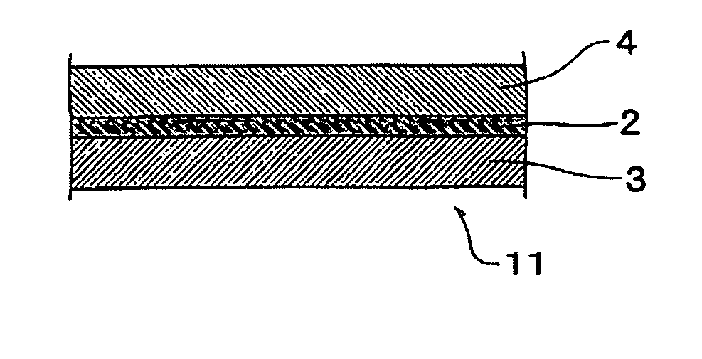
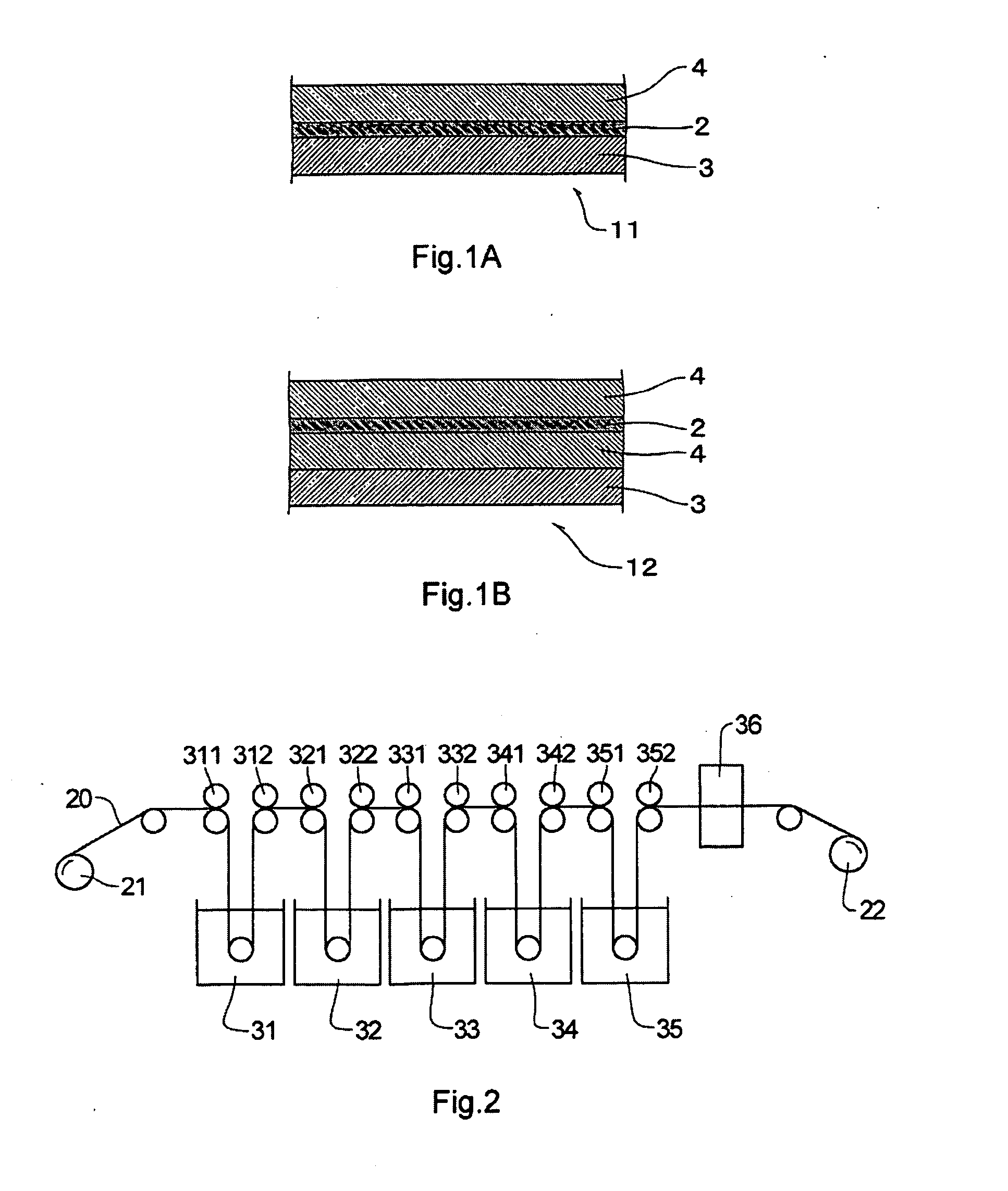
[0168]The above continuous retardation film (b1) was laminated on one surface of the above continuous polarizer (a1) through a water-soluble adhesive layer (a thickness of 1 μm) containing a polyvinyl alcohol-based polymer [trade name “GOHSEFIMER Z200”, manufactured by Nippon Synthetic Chemical Industry Co., Ltd.] as the main component interposed therebetween. However, the continuous retardation film (b1) was disposed so that the slow axis direction of the retardation film (b1) was at an angle of approximately 90° with the absorption axis direction of the continuous polarizer (a1).

[0169]On the other hand, a triacetylcellulose film having a thickness of 80 μm was laminated on the other surface of the above continuous polarizer (a1) through the same water-soluble adhesive layer (a thickness of 1 μm) interposed therebetween. In this way, a continuous optical laminated film having a width of 1700 mm was produced. This continuous optical laminated film was die-cut into a rectangle having...

example 2

[0170]Each of the films was laminated in the same manner as in Example 1 except for replacing the continuous retardation film (b1) with the continuous retardation film (b2) to produce a continuous optical laminated film having a width of 1700 mm. This continuous optical laminated film was die-cut into a rectangle having a diagonal line of 40-inch with a Thomson blade to produce a rectangular optical laminated film (x2).


PUM

PropertyMeasurementUnit
transmittanceaaaaaaaaaa
thicknessaaaaaaaaaa

Abstract

The optical laminated film of the present invention comprises a polarizer and a retardation film laminated on one surface of the polarizer, in which the polarizer has a drawn film of a hydrophilic polymer containing a dichroic material. An in-plane birefringence index (Δnxy[1000]) of this polarizer at wavelength of 1000 nm is from 0.01 to 0.03, and the retardation film is a film such that an index ellipsoid satisfies the relation of nx>ny≧nz. The retardation film is disposed so that the slow axis direction of the retardation film is substantially orthogonal to the absorption axis direction of the above polarizer.
The optical laminated film of the present invention may increase contrast ratio in the case of being used for a liquid crystal display, for example.

Description

TECHNICAL FIELD[0001]The present invention relates to an optical laminated film used for a liquid crystal display and the like, a method for producing thereof, and a liquid crystal display provided with the optical laminated film.BACKGROUND ART[0002]A liquid crystal display is utilized for various uses while making use of characteristics thereof such as light weight, thin type, low power consumption, and the like. This is used for portable telephones, monitors, televisions, and the like for example. In recent years, for example, with regard to a liquid crystal display used for televisions, upsizing of the screen has rapidly progressed. For example, a liquid crystal television having a diagonal screen of 65-inch has been put to practical use. Under such a market trend, upsizing of an optical film utilized for the liquid crystal display has been urgent business.[0003]An optical laminated film such that a polarizer and an optical compensation film composed of a drawn film of a thermopl...

Claims


Application Information

Patent Timeline
Patent Type & Authority Applications(United States)
IPC IPC(8): G02F1/13363G02B1/08B29C47/06
CPCG02B5/3033G02B5/3083G02F1/13363
Inventor NAGASE, JUNICHIFUTAMURA, KAZUNORIYOSHIMI, HIROYUKIHAYASHI, MASAKI
Owner NITTO DENKO CORP
Why Eureka
Try Eureka