Camera-style lidar setup
- Summary
- Abstract
- Description
- Claims
- Application Information
AI Technical Summary
Benefits of technology
Problems solved by technology
Method used
Image

Examples
Embodiment Construction
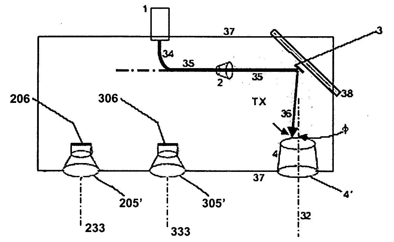
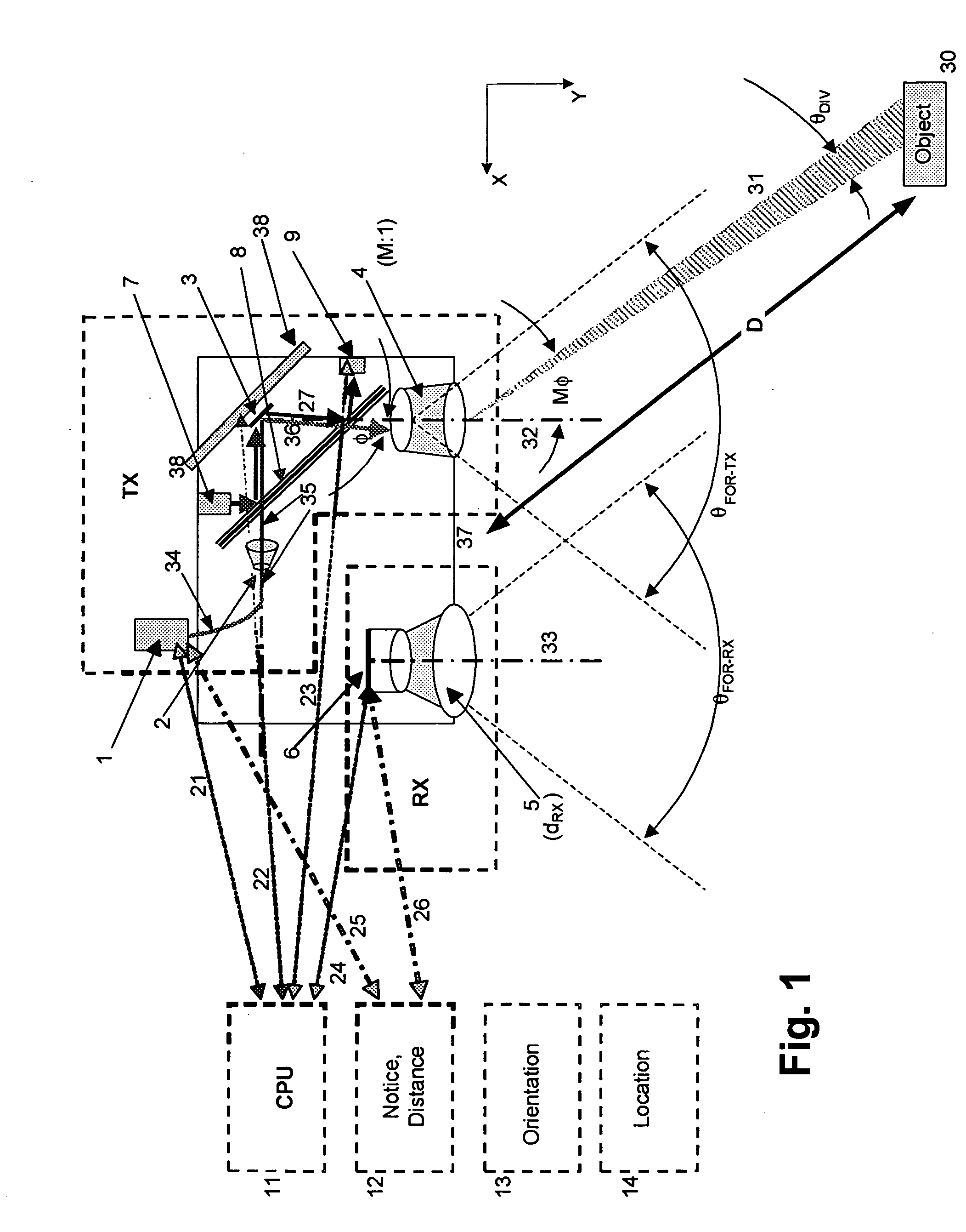
[0070]A reflective element or module 3 (FIGS. 1 and 2)—which can be a small, single mirror, or a MEMS scan mirror, or a MEMS scan-mirror array—can be used for projection but not for capturing the reflected beam. As in previous work of Bowker, Lubard and McLean, as well as our own earlier innovations mentioned above, it is possible to accumulate data that give, in effect, a three-dimensional impression of a region by aggregating numerous two-dimensional or flying-spot data elements.
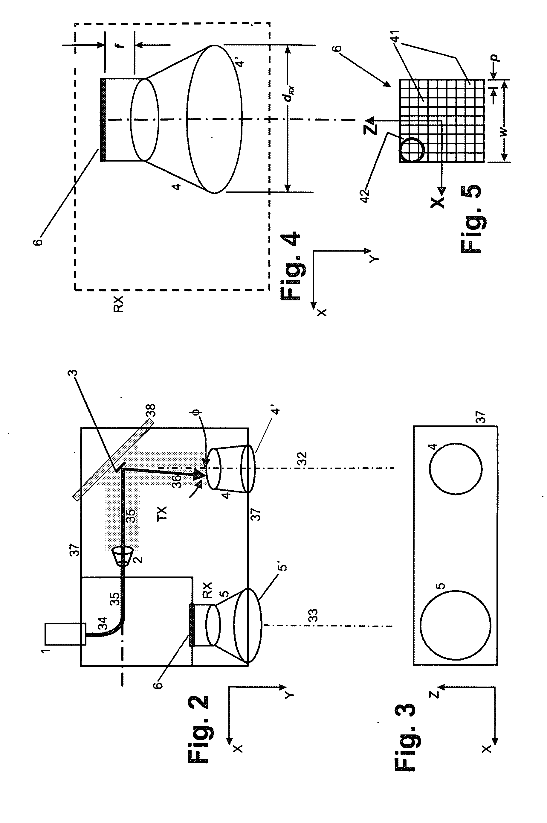
[0071]The lidar system includes an afocal MEMS beamsteering (AMBS) transmitter TX (FIGS. 1, 2 and 4), and a receiver RX. The AMBS transmitter system (hereinafter “AMBS-TX”) and the receiver system address a common field of regard (“FOR”), with angular extent θFOR, about the X and Z axes (FIGS. 3 and 5). More precisely, the angles θ (FIG. 1) that are actually shown represent horizontal angular position θX; whereas the orthogonal angles representing vertical angular position θZ are in and out of the plane of...
PUM
 Abstract
Description
Claims
Application Information
 - Generate Ideas
- Intellectual Property
- Life Sciences
- Materials
- Tech Scout
- Unparalleled Data Quality
- Higher Quality Content
- 60% Fewer Hallucinations
Browse by: Latest US Patents, China's latest patents, Technical Efficacy Thesaurus, Application Domain, Technology Topic, Popular Technical Reports.
© 2025 PatSnap. All rights reserved.Legal|Privacy policy|Modern Slavery Act Transparency Statement|Sitemap|About US| Contact US: help@patsnap.com