Heat Sink Mount for Providing Non-Rigid Support of Overhanging Portions of Heat Sink

a heat sink and non-rigid technology, applied in the direction of electrical apparatus casings/cabinets/drawers, instruments, semiconductor/solid-state device details, etc., can solve problems such as “at risk” or overhanging portions of heat sinks

Active Publication Date: 2010-07-01
ORACLE INT CORP
View PDF14 Cites 16 Cited by
  • Summary
  • Abstract
  • Description
  • Claims
  • Application Information

AI Technical Summary

Benefits of technology

[0009]Briefly, the above and other issues are addressed with a low force mount for use as a secondary or augmentation to a primary mount for heat sinks used to remove heat from processors and other electronics components. The low force mount may be thought of as a secondary heat sink mounting assembly that controls dynamic forces that may be applied to a heat sink during shipping and operations and also provides support of cantilevered or overhanging portions of a heat sink. Heat sinks are often supported proximate to a processor / CPU by a primary mount, but, due to demands for more heat transfer surface area, heat sinks may extend outward from the primary mount significant distances, which creates “at risk” or overhanging portions of the heat sink (or of the base plate or heat transfer plate of the heat sink). Embodiments of secondary heat sink mounting assemblies provided here include damping elements that are use to support one or more overhanging portions of the heat sink near its cantilevered edge(s). The damping elements may take many shapes and sizes, but the damping elements or dampers generally include a body formed of or including elastomeric material, such as low durometer rubber, that abuts the base plate of the heat sink to absorb energy (e.g., to dampen vibrations) from the heat sink and to allow for manufacturing / assembly tolerances (e.g., avoid applying a static load on the heat sink as occurs with some rigid support designs).

Problems solved by technology

Heat sinks are often supported proximate to a processor / CPU by a primary mount, but, due to demands for more heat transfer surface area, heat sinks may extend outward from the primary mount significant distances, which creates “at risk” or overhanging portions of the heat sink (or of the base plate or heat transfer plate of the heat sink).

Method used


Image

  • Heat Sink Mount for Providing Non-Rigid Support of Overhanging Portions of Heat Sink
  • Heat Sink Mount for Providing Non-Rigid Support of Overhanging Portions of Heat Sink
  • Heat Sink Mount for Providing Non-Rigid Support of Overhanging Portions of Heat Sink

Examples


Embodiment Construction

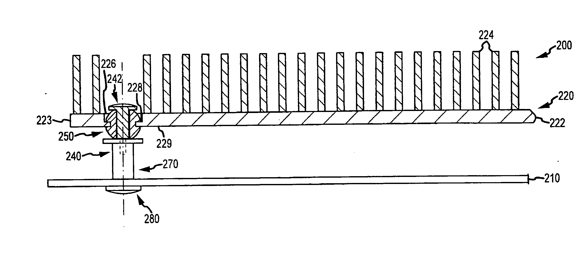
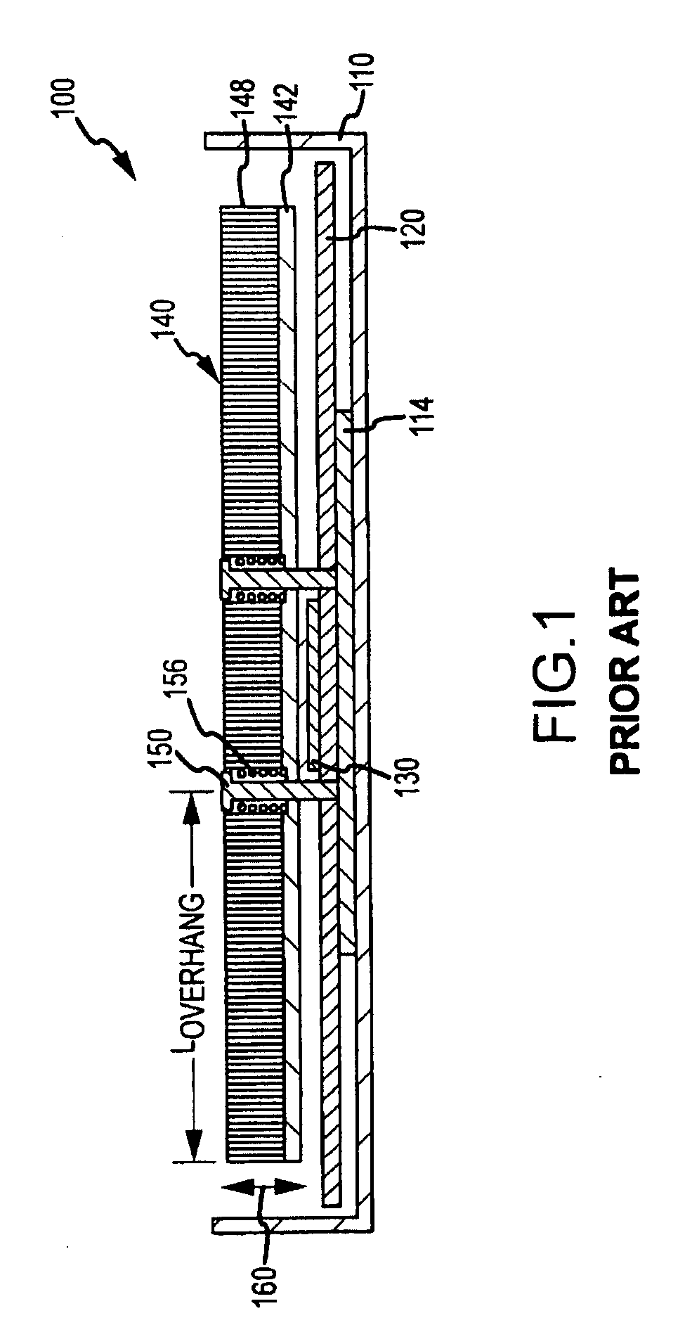
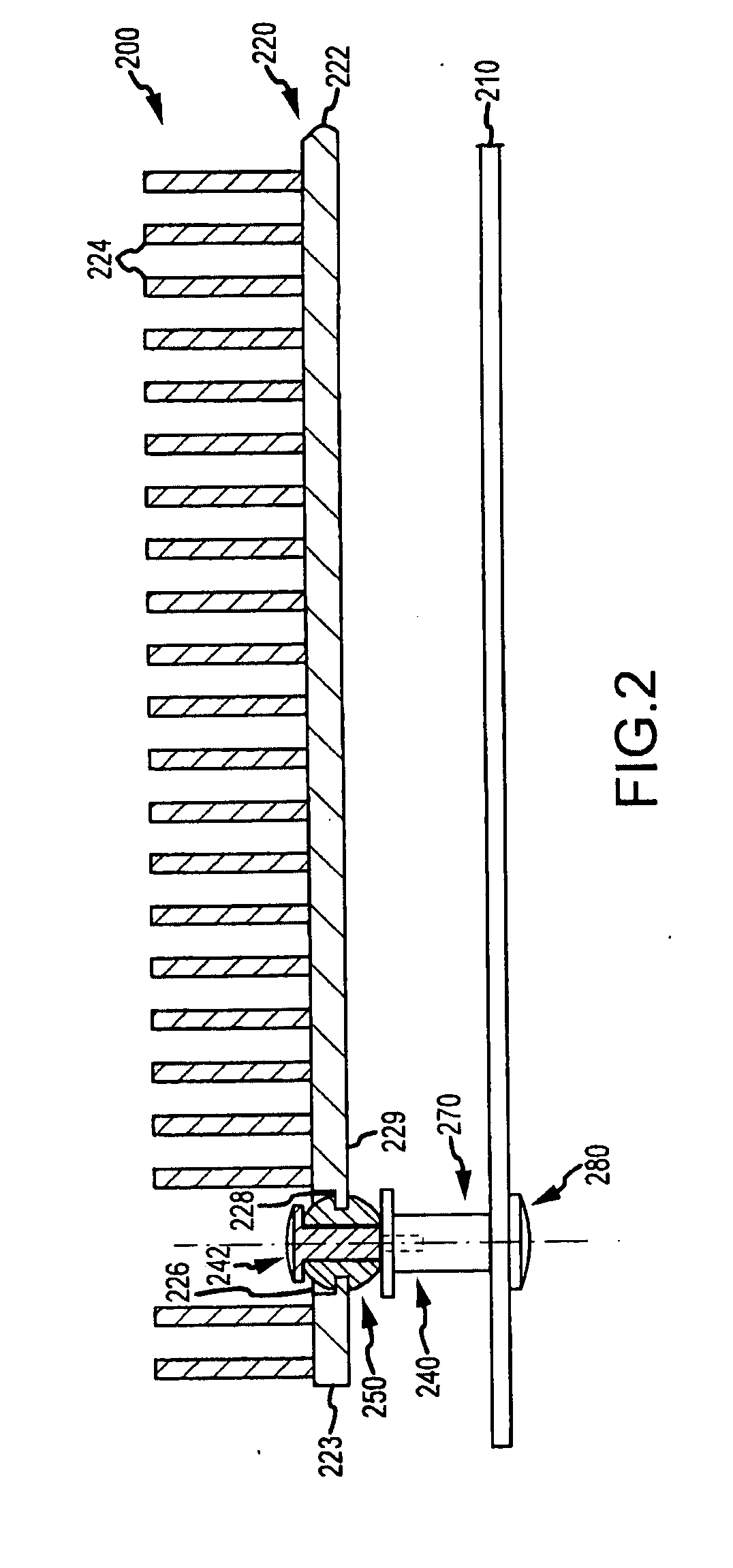
[0022]Briefly, embodiments of the present invention are directed to mounting assemblies for use with heat sinks that are used to cool electronic components, e.g., a CPU or the like, within a chassis or box such as a computer system / server housing. The mounting assemblies may be thought of as low-force, outboard heat sink mounts that are provided to augment primary heat sink mounts (and, typically, to not interfere or effect these primary mounts) to absorb dynamic forces experienced by outboard or overhanging portions of heat sinks. The present invention is also directed toward computing devices such as servers that incorporate the heat sink mounting assemblies described, and the following description illustrates partial views of such computing systems to stress features of the mounting assemblies. However, it should be understood that these assemblies can be implemented to modify the computing system 100 of FIG. 1 (e.g., the mounting assemblies may be used to supplement the primary ...


PUM


Abstract

A computer adapted for force-air cooling of a processor. The computer includes a board supporting the processor and a heat sink mounted such with its base plate contacting the processor. A primary mount supports the heat sink near the processor, and a portion of the heat sink base plate extends outward a distance or overhang length from the primary mount to an edge. The apparatus includes a secondary heat sink mounting assembly supported upon the processor board that includes a damping element with an resilient body positioned proximate to the edge of the base plate, whereby the body abuts the base plate during movement of the base plate toward the board, e.g., upon application of a dynamic or shock load that causes the overhanging portions of the base plate of the heat sink to vibrate or oscillate about the support locations of the primary mount.

Description

BACKGROUND OF THE INVENTION[0001]1. Field of the Invention[0002]The present invention relates, in general, to methods and systems for cooling processors (e.g., central processing units or CPUs) in servers and other computing devices, and, more particularly, to methods, assemblies, and components for mounting heat sinks in desired heat transfer contact with a CPU while allowing for manufacturing tolerances and for stresses and / or forces applied to the heat sink during shipping and operation of the computing device.[0003]2. Relevant Background[0004]Removal of heat has become one of the most important challenges facing computer designers as failure to adequately cool devices can cause failure or operating problems. The rate of power dissipation from electronics components such as from processors (or CPUs) in high-performance server units continues to increase. In most cases, air cooling is used to remove heat from a heat generating surface of a CPU, a motherboard, and other components ...

Claims


Application Information

Patent Timeline
Patent Type & Authority Applications(United States)
IPC IPC(8): G06F1/20H05K7/20
CPCH01L23/40H01L23/4006H01L23/467H01L2023/4062H01L2023/4081H01L2023/4087H01L2924/0002H01L2924/00
Inventor KEARNS, DONALD A.
Owner ORACLE INT CORP
Why Eureka
Try Eureka