Switching power supply circuit

Active Publication Date: 2010-07-01
FUJI ELECTRIC CO LTD
View PDF7 Cites 94 Cited by
  • Summary
  • Abstract
  • Description
  • Claims
  • Application Information

AI Technical Summary

Benefits of technology

[0029]The switching power supply circuit can further include a power factor controller configured to control an ON-period of the switching device based on an error signal obtained by amplifying a difference between the feedback voltage of the DC voltage output and a reference voltage. To control the ON-period, the power factor controller can be configured to compare the feedback voltage with a first protection voltage as the reference voltage,

Problems solved by technology

If power factor improvement is not conducted, a high frequency current component and a high frequency voltage component will be caused in the rectifier circuit, and the power factor will be impaired, since a current flows only at the peak of the input voltage to a smoothing capacitor connected to the rectifier circuit.
Therefore, the inductance becomes too large in the switching power. supply circuit, which can feed a high wattage of DC power.
However, the deformation due to the magneto striction has not been completely removed yet.
On the other hand, if the switching operation is stopped suddenly, a vibration that releases the magneto striction energy at the mechanical an

Method used


Image

  • Switching power supply circuit
  • Switching power supply circuit
  • Switching power supply circuit

Examples


Example

[0038]The invention will now be described in more detail by way of example with reference to the embodiments shown in the accompanying figures. It should be kept in mind that the following described embodiments are only presented by way of example and should not be construed as limiting the inventive concept to any particular physical configuration.

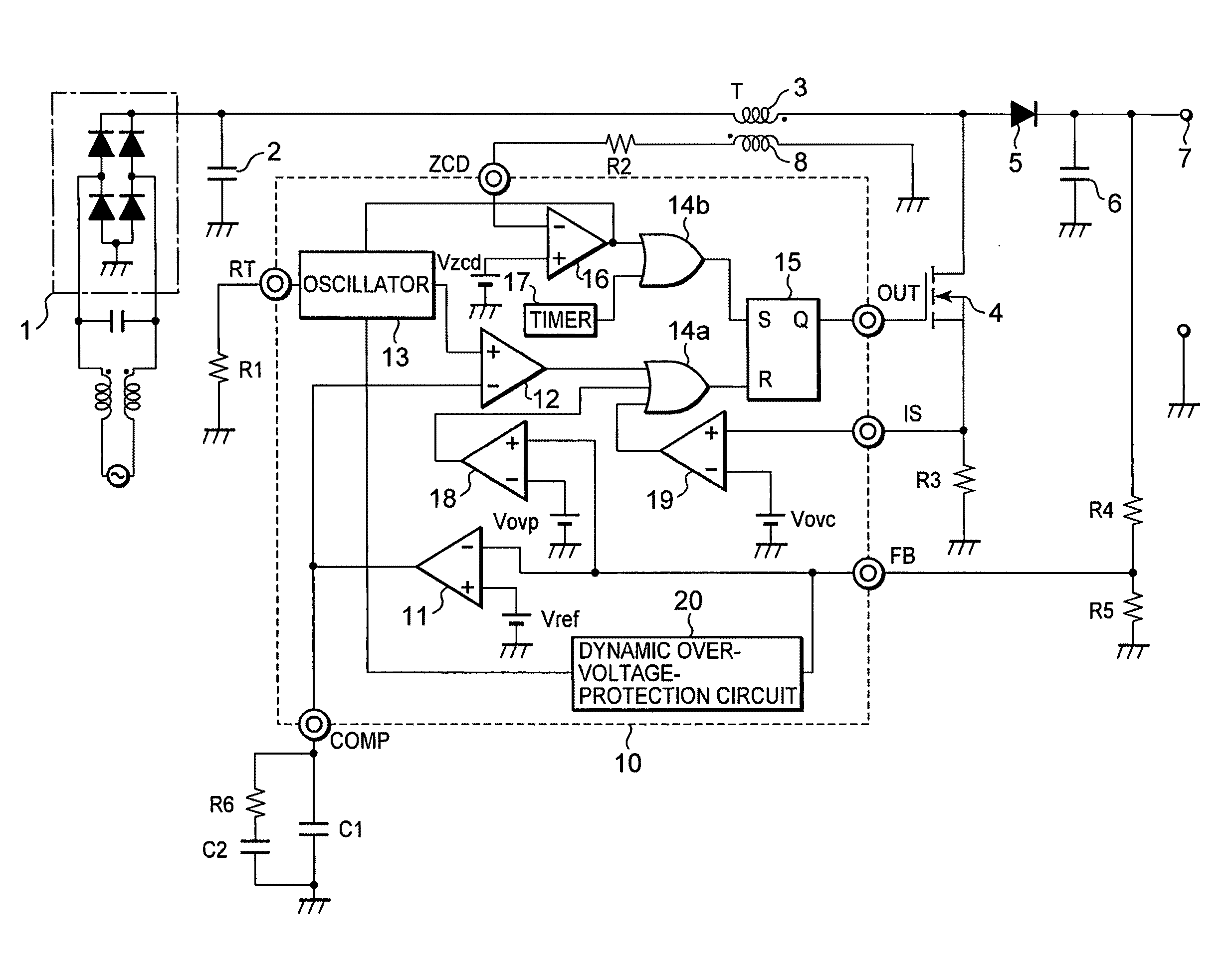
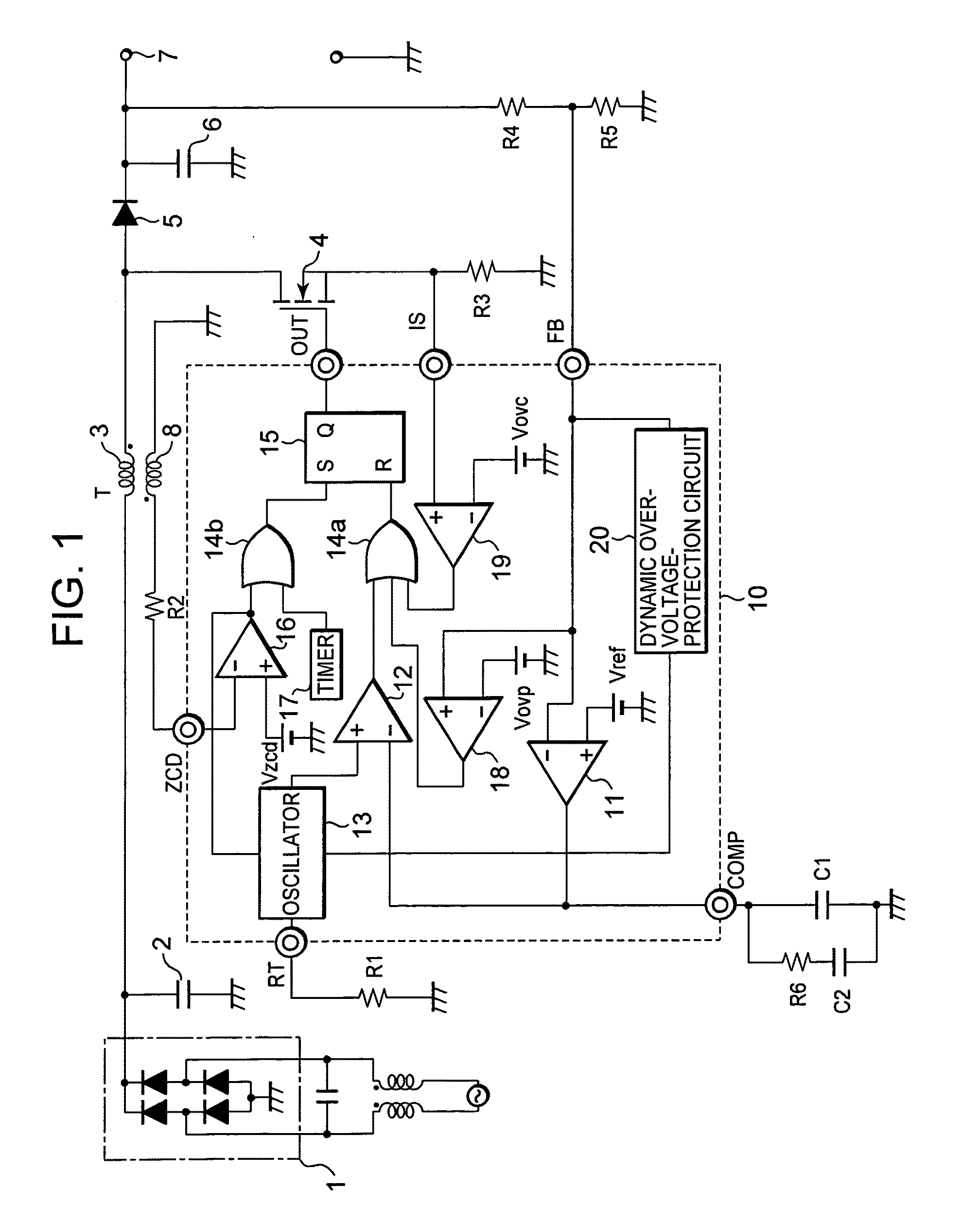
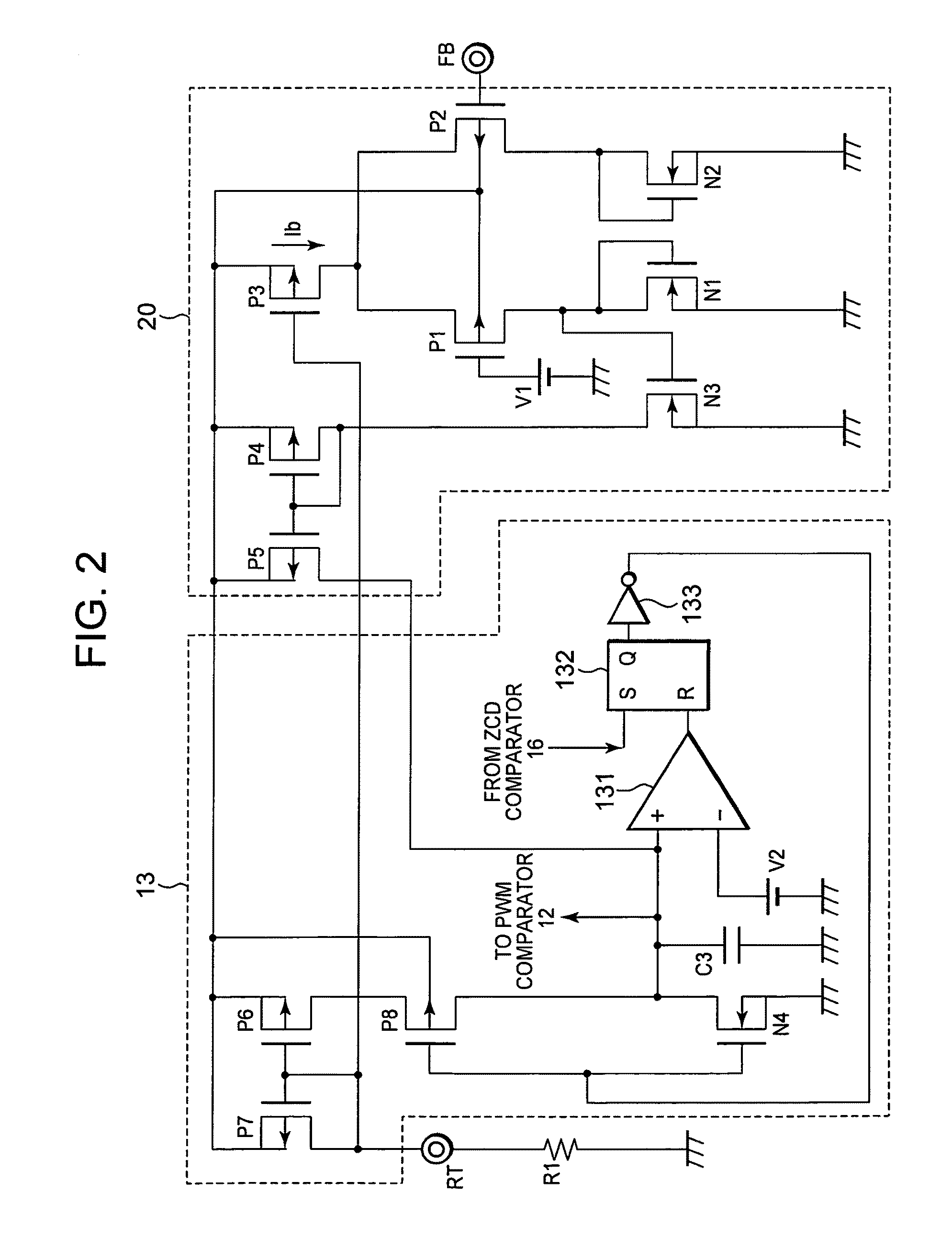
[0039]FIG. 1 is a block circuit diagram showing a switching power supply circuit employing a fixed-ON-period control method according to an exemplary embodiment. FIG. 2 is a block circuit diagram showing detailed configurations of a dynamic over-voltage-protection circuit and an oscillator in the switching power supply circuit shown in FIG. 1.

[0040]The switching power supply circuit shown in FIG. 1 is configured by adding dynamic over-voltage-protection circuit 20 to PFC circuit 10 to the conventional switching power supply circuit (shown in FIG. 6). Dynamic over-voltage-protection circuit 20 monitors the feedback voltage from FB terminal...


PUM


Abstract

A switching power supply circuit that obtains a predetermined DC voltage output from an input AC power supply includes a full-wave rectifier and a boost circuit connected to the rectifier. The boost circuit generates a DC output having a predetermined voltage value from the rectifier output. A power factor improving circuit controls an ON-period of an output transistor of the boost circuit, based on feedback of the DC voltage output, and a dynamic over-voltage-protection circuit controls the ON-period of the output transistor as it performs a switching operation. The switching power supply circuit facilitates an over-voltage-protection function that prevents inductor buzzing with an integrated circuit having a small number of pins.

Description

FIELD OF THE INVENTION[0001]Embodiments of the present invention relate to a switching power supply circuit that obtains a predetermined DC voltage output from an AC input power supply. Specifically, the embodiments of the invention relate to a switching power supply circuit that boosts a commercial AC power supply with an inductance element and facilitates improving the power factor.BACKGROUND[0002]Many types of electronic equipment, to which a commercial AC power supply (AC 100 V) is fed, use a switching power supply circuit to obtain a DC power supply for driving the internal electronic circuits of the electronic equipment. Therefore, it is necessary for the switching power supply circuit to provide a rectifier circuit for converting the commercial AC power supply to a DC power supply. If power factor improvement is not conducted, a high frequency current component and a high frequency voltage component will be caused in the rectifier circuit, and the power factor will be impaire...

Claims


Application Information

Patent Timeline
IPC IPC(8): H02M7/06
CPCH02M1/4225Y02B70/126Y02B70/10
Inventor SUGAWARA, TAKATO
Owner FUJI ELECTRIC CO LTD
Why Eureka
Try Eureka