Wide-coverage x-ray source with dual-sided target

a dual-sided target and wide-coverage technology, applied in the field of computed tomography systems, can solve problems such as inacceptable levels of image artifacts

Active Publication Date: 2010-07-01
GENERAL ELECTRIC CO
View PDF4 Cites 12 Cited by
  • Summary
  • Abstract
  • Description
  • Claims
  • Application Information

AI Technical Summary

Problems solved by technology

However, for larger axial coverage, unacceptable levels of image artifacts are created when a single x-ray source is used in the scanning system.

Method used


Image

  • Wide-coverage x-ray source with dual-sided target
  • Wide-coverage x-ray source with dual-sided target
  • Wide-coverage x-ray source with dual-sided target

Examples


Embodiment Construction

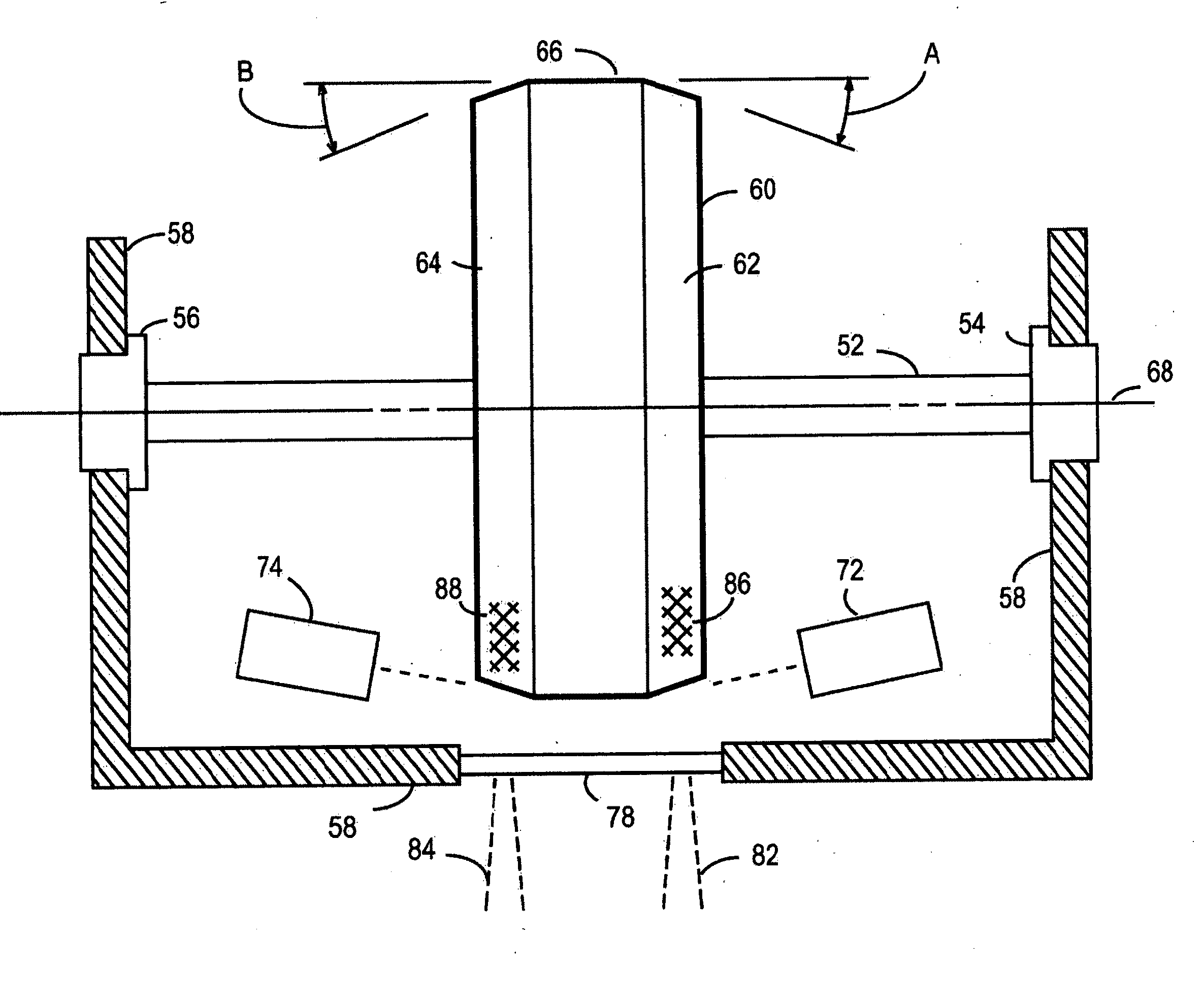
[0019]This invention includes a rotating anode with a dual-beveled annulus configuration that provides for two independently-controlled focal spots, one on each annulus. For many representative scanning sequences, this provides for greater flexibility in operation as alternating x-ray source activation can be used to optimize image acquisition. A yoke structure supports electron beam emission cathodes from a single high-voltage insulator in a housing wall. In addition, a high-load capacity straddle-type bearing support arrangement for the rotating anode is able to withstand high gantry rotation speeds.

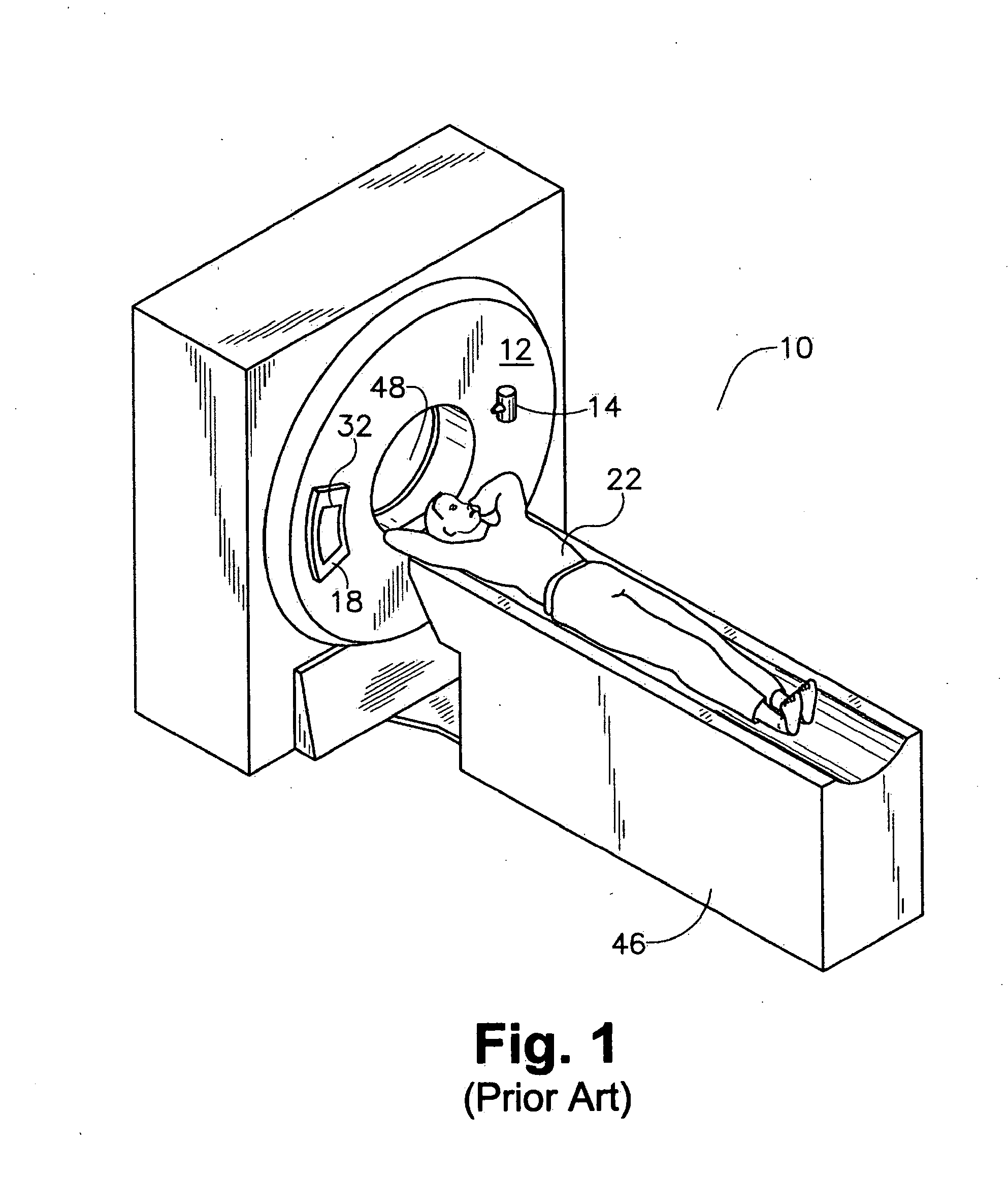
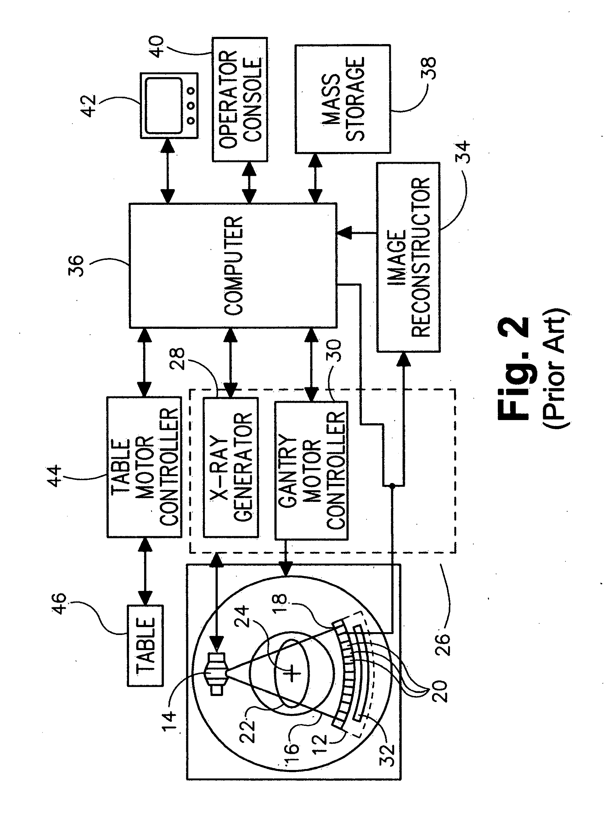
[0020]There is shown in the isometric diagrammatical illustration of FIG. 1 a “third generation” CT imaging system 10 configured to perform computed tomography imaging by means of photon counting and energy discrimination of x-rays at high flux rates, as is known in the relevant art. The CT imaging system 10 comprises a gantry 12, with a collimator assembly 18, a data acquisition syste...


PUM


Abstract

An x-ray source is disclosed comprising: an anode disk with first and second beveled annuli at a periphery of the anode disk, the anode disk rotatably coupled to a housing structure via a support shaft; first and second cathodes mounted to a yoke support structure, the yoke support structure configured to direct cathode emissions at x-ray generating material disposed on the beveled annuli; and a high-voltage insulator configured to electrically insulate the yoke support structure from the housing structure.

Description

BACKGROUND OF THE INVENTION[0001]The subject matter disclosed herein relates to computed tomography systems and, in particular, to x-ray sources for such systems.[0002]Future Computed Tomography (CT) medical imaging systems will be designed to perform volumetric, “organ-in-a-rotation” scanning. This requirement imposes significant increases in temporal resolution and axial coverage. In turn, this necessitates that the component x-ray tube produce x-rays that cover an increased axial extent with uniform intensity and that the tube be able to withstand mechanical stresses incurred as a result of faster gantry rotation speeds in the CT medical imaging (hereinafter scanning) systems.[0003]CT imaging involves computer-aided reconstruction of an image internal to an object or a human patient, where the reconstructed image is generated from a plurality of views taken at a succession of different scan angles as the gantry rotates around the object or the patient. In an ideal scanning proced...

Claims


Application Information

Patent Timeline
Patent Type & Authority Applications(United States)
IPC IPC(8): H05G1/60H01J35/06H01J35/00
CPCH01J35/10H01J2235/068H01J2235/086
Inventor VERMILYEA, MARK E.SIMPSON, JAMES E.
Owner GENERAL ELECTRIC CO
Why Eureka
Try Eureka